Table of Contents
Advertisement
Quick Links
Advertisement
Table of Contents

Subscribe to Our Youtube Channel
Related Manuals for F&F LE-03MQ CT


Summary of Contents for F&F LE-03MQ CT
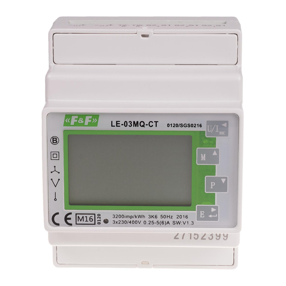
- Page 1 F&F Filipowski sp.j. ul. Konstantynowska 79/81 95-200 Pabianice Tel./fax (42) 215 23 83, 227 09 71 e-mail: biuro@fif.com.pl www.fif.com.pl LE-03MQ CT Electric energy meter 1-phase/ 3-phase Bidirectional with network parameters analysis User manual v. 4.8 (211029) www.fif.com.pl...
-
Page 2: Table Of Contents
LE-03MQ CT – User manual CONTENTS 1. PURPOSE............................... 4 2. UNIT CHARACTERISTIC ..........................4 2.1. Measured values ................................4 2.2. Current transformers (CT) .............................. 4 2.3. RS-485 communication port and Modbus RTU protocole ..................... 5 2.4. Pulse output ..................................5 3. - Page 3 LE-03MQ CT – User manual 5.2.7. Backlit setup ................................19 5.2.8. Measuring system ..............................19 5.2.9. CLR ................................... 20 5.2.10. Change password ..............................21 6. TECHNICAL SPECIFICATION ........................22 6.1. Measured parameters ..............................22 6.1.1. Voltages and currents .............................. 22 6.1.2.
-
Page 4: Purpose
LE-03MQ CT - User manual 1. PURPOSE LE-03MQ CT is a static (electronic) calibrated electricity meter of single-phase or three-phase alternating current in a direct system. It is used for reading and recording of consumed electric energy and mains parameters with remote readout via a wired RS-485 network. The meter works with current transformers (CT) with 1 A or 5 A secondary current. -
Page 5: Rs-485 Communication Port And Modbus Rtu Protocole
LE-03MQ CT - User manual 2.3. RS-485 communication port and Modbus RTU protocole The meter is equipped RS-485 port with Modbus RTU protocole. The RS-485 communication port allows you to connect meters into a network of remote reading. 2.4. Pulse output The meter has two pulse outputs for mapping the counting of active and reactive energy. -
Page 6: Operator Panel
LE-03MQ CT - User manual 4. OPERATOR PANEL Buttons features: Select the voltage and current display screens. In set up mode, this is the "Left" or "Back" button. Select the frequency and power factor display screens. In set up mode, this is the "Up" button. -
Page 7: Frequency, Power Factor And Demand
LE-03MQ CT - User manual Current THD% for each phase. 4.2. Frequency, power factor and demand Each successive pressing of the button selects a new range: Frequency and power factor (total). Power factor of each phase. Maximum power demand. Maximum current demand. -
Page 8: Power
LE-03MQ CT - User manual 4.3. Power Each successive pressing of the button select a new range: Instantaneous active power in kW. Instantaneous reactive power in kVAr. Instantaneous volt-amps in kVA. Total: kW, kvar, kVA... -
Page 9: Energy Measurements
LE-03MQ CT - User manual 4.4. Energy measurements Each successive pressing of the button selects a new range: Imported active energy in kWh Exported active energy in kWh Imported reactive energy in kVArh Exported reactive energy in kVArh Total active energy in kWh Total reactive energy in kVArh The total value of the given energy is presented in two rows. -
Page 10: Setup
LE-03MQ CT - User manual The top row presents the higher values, the bottom row presents the lower values + fractional value. For example: Indications: 0027 - top row; 845.3 - bottom row presents the value of 27845.3 kWh. 5. SETUP 5.1. -
Page 11: Setup Parameters
LE-03MQ CT - User manual 5.2. Setup parameters 5.2.1. Entry into configuration menu To enter setup mode, pressing the button for 2 seconds, until the password screen appears. Settung up is password-protected so you must enter the correct password (default "1000") before processing. -
Page 12: Baud Rate
LE-03MQ CT - User manual buttons to choose Modbus address (001 to 247). Press button to confirm the selection. Press button to return the main set up menu. 5.2.2.2. Baud rate From the set up menu, use buttons to select the Baud rate option. -
Page 13: Parity
LE-03MQ CT - User manual 5.2.2.3. Parity From the set up menu, use buttons to select the parity option. Press to enter the selection routine. The current setting will flash. buttons to choose parity EVEN/ODD/NONE (default). Press button to confirm selection. -
Page 14: Current Transformers
LE-03MQ CT - User manual buttons to choose stop bits: 2 or 1. NOTE: Default value is 1. Only in case parity set up NONE, to change stop bits to 2. Press to confirm the selection. Press to return to the main set up menu. -
Page 15: Measuring Voltage
LE-03MQ CT - User manual 5.2.4. Measurement voltage Setting the value of the input voltage directly or through transformers. For half-indirect 1- or 3-phase measurement set the value PT2 to 400 and PTrate to 1. Use the buttons in the configuration menu to select the PT option. -
Page 16: Pulse Output
LE-03MQ CT - User manual 5.2.5. Pulse output Pulse output configuration no. 1. 5.2.5.1. Energy setup The output can be set to provide a pulse for a definied amount of energy active (kWh) or reactive (kvarh). From the setup menu, use buttons to select the pulse output option. -
Page 17: Pulse Rate
LE-03MQ CT - User manual 5.2.5.2. Pulse rate Setup value option kWh/kvarh per 1 pulse. Values: 0.01 / 0.1 / 110 / 100. From the setup menu, use buttons to select the pulse rate option. Press to enter the selection routine. -
Page 18: Demand Integration Time (Dit)
LE-03MQ CT - User manual 5.2.6. DIT - Demand Integration Time The options are: 5, 10, 15, 30, 60 minutes. From the setup menu, use buttons, to select the DIT option. The screen will show the currently selected integration time. -
Page 19: Backlit Setup
LE-03MQ CT - User manual 5.2.7. Backlit setup The meter allows you to set the time of the backlight. Time: 0 / 5 / 10 / 30 / 60 / 120 minutes. Value 0 means that the backlight is always on. -
Page 20: Clr
LE-03MQ CT - User manual buttons to select the required system option: 1P2(W), 3P3(W), 3P4(W). Press to confirm selection. SET indicator will appear. Press to exit the system selection routine and return to the menu. SET will disappear and you will be returned to the main set up menu. -
Page 21: Change Password
LE-03MQ CT - User manual 5.2.10. Change password Press buttons to choose the change password option. Press and hold to enter the change password routine. The new password screen will appear with the first digit flashing. buttons to set the first digit and press to confirm your selection. -
Page 22: Technical Specification
LE-03MQ CT - User manual 6. TECHNICAL SPECIFICATION 6.1. Measured parameters The unit can monitor and display the following parameters of: 1P2W – 1-phase 2-wire system (230V+N) 3P3W – 3-phases 3-wire system (3×400V; without neutral wire) 3P4W – 3-phases 4-wire system (3×230V+N) 6.1.1. -
Page 23: Energy Measurements
LE-03MQ CT - User manual 6.1.3. Energy measurements Imported/exported active energy: 0÷9999999,9 kWh Imported/exported reactive energy: 0÷9999999,9 kVArh Total active energy: 0÷9999999,9 kWh Total reactive energy: 0÷9999999,9 kVArh 6.2. Terminal Current inputs 2.5mm² screw terminals Voltage inputs 2.5mm²... -
Page 24: Pulse Outputs
LE-03MQ CT - User manual 6.6. Pulse outputs Outputs type: OC (open collector); 27V DC/50mA Pulse: Pulse output 1 is configurable: for kWh or kvarh. Value set up kWh/kvarh per 1 pulse: 0,01 = 10 Wh/VArh 0.1 = 100 Wh/VArh... -
Page 25: Environment
LE-03MQ CT - User manual 6.9. Environment -25÷55°C Operating temperature -40÷70°C Storage temperature Relative humidity 0÷95%, non-condensing Up to 3000 m Altitude Warm up time 1 minute 10÷50Hz, IEC 60068-2-6, 2 g Wibration Limitation 30g in 3 planes 6.10. Structure... -
Page 26: Dimensions
LE-03MQ CT - User manual 7. DIMENSIONS 8. WIRING DIAGRAM 8.1. Meter's power supply The meter is not powered from the voltage measurement inputs. It requires separate power supply from any phase of the measuring system. -
Page 27: Measuring Systems
LE-03MQ CT - User manual 8.2. Measuring systems Single phase two wires system Three phases three wires system... -
Page 28: Modbus Protocole Registers
LE-03MQ CT - User manual Three phases four wires system 9. MODBUS PROTOCOL REGISTERS 9.1. Input registers Input registers are used to indicate the present values of the measured and calculated electrical quantities. Each parameter is held in two consecutive 16-bit register (FLOAT). The following table details the 3X register address, and the values of the address bytes within the message. - Page 29 LE-03MQ CT - User manual Register Measuring parameter System address (Dec/Hex) Description Units 3P4W 3P3W 1P2W 0 / 00 L1 (L-N) Phase voltage √ √ 2 / 02 L2 (L-N) Phase voltage √ 4 / 04 L3 (L-N) Phase voltage √...
- Page 30 LE-03MQ CT - User manual kWh/ 72 / 48 Imported active energy kWH/ 74 / 4A Exported active energy kVarh/ 76 / 4C Imported reactive energy MVarh kVarh/ 78 / 4A Exported reactive energy MVarh kVah/ 80 / 50 Apparent power...
- Page 31 LE-03MQ CT - User manual 242 / F2 Phase 2 current THD 244 / F4 Phase 3 current THD Average line to neutral volts THD 248 / F8 Average line current THD 250 / FA 258 / 102 Phase 1 current demand...
-
Page 32: Setup Registers
LE-03MQ CT - User manual 9.2. Setup registers Holding registers used store display instrument configuration settings. All holding registers not listed in the table below should be considered as reserved for manufacturer use and attempt should made modify their values. The holding register parameters may be viewed or changed using the Modbus Protocol. - Page 33 LE-03MQ CT - User manual Write the network port node address: Network 1 to 247 for MODBUS Protocol, default 1. 20 / 14 node Requires a restart to become effective. Write pulse divisor index: n = 1 to 5 1--0.01kw/pulse Pulse 2--0.1kw/pulse...
Need help?
Do you have a question about the LE-03MQ CT and is the answer not in the manual?
Questions and answers