Table of Contents
Advertisement
Quick Links
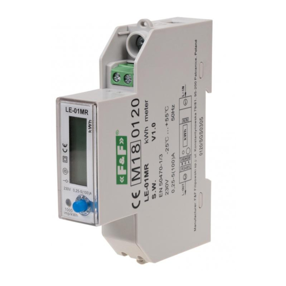
LE-01MR
Electric energy meter,
1-phase
Do not dispose of this device in the trash along with other waste!
According to the Law on Waste, electro coming from households free of charge and can
give any amount to up to that end point of collec� on, as well as to store the occasion of
the purchase of new equipment (in accordance with the principle of old-for-new, regard-
less of brand). Electro thrown in the trash or abandoned in nature, pose a threat to the
environment and human health.
Compliance
MID Directive
Certificate
Purpose
The LE-01MR is a static (electronic) calibrated electricity meter
of single-phase alternating current in direct system.
It is designed to indicate and register the consumed electricity
and parame-ters of the power supply network with the option of
remote reading of indications via RS-485 network.
Functioning
The LE-01MR meter precisely measures the amount of consu-
med electricity under the influence of flowing current and ap-
plied voltage. Power consumption is indicated by the flashing
LED (1000 pulses/kWh). In addition, the meter measures the pa-
rameters of the supply network and the temperature of its own
system. The values are indicated cyclically on the LCD display.
F&F Filipowski sp. j.
Konstantynowska 79/81, 95-200 Pabianice, POLAND
phone/fax (+48 42) 215 23 83 / (+48 42) 227 09 71
www.fif.com.pl; e-mail: biuro@fif.com.pl
2014/32/EU
0120/SGS0305
- 1 -
Advertisement
Table of Contents

Related Manuals for F&F LE-01MR


Summary of Contents for F&F LE-01MR
- Page 1 Certificate 0120/SGS0305 Purpose The LE-01MR is a static (electronic) calibrated electricity meter of single-phase alternating current in direct system. It is designed to indicate and register the consumed electricity and parame-ters of the power supply network with the option of remote reading of indications via RS-485 network.
- Page 2 The parameter is changed by default every 5 seconds or at the frequency set by the user and manually, using the button on the front of the casing of the meter. The display is active when the indicator power is on. The meter operates in the communication network as a Slave device.
- Page 3 Meter address Change of meter address is done via the RS-485 port using the Modbus RTU protocol command to set the desired value in the meter register. The default meter address: 1. Meter number The meter is marked with individual serial number allowing its unambiguous identification.
- Page 4 Front panel - 4 -...
- Page 5 Wiring diagram power input power output N-wire neutral RS-485 output (A) RS-485 output (GND) RS-485 output (B) - 5 -...
- Page 6 Mounting 1. Disconnect the power supply. 2. Mount the indicator on the rail in the distribution box. 3. Connect the neutral wire to terminal N. 4. Connect the input phase to terminal 1. 5. Connect the measured circuit or single receiver to terminal 3 (output phase L) and to N.
- Page 7 communication port RS-485 communication protocol Modbus RTU transmission parameters 1200, 2400, 4800, 9600* bps parity NONE, ODD, EVEN* stop bits read-out signalling red LED working temperature -25÷55°C terminal 100 A 25 mm² screw terminals RS-485 1 mm² screw terminals tightening torque 0.4 Nm dimensions 1 module (18 mm)
- Page 8 Dimensions Warranty F&F products are covered by a 24-month warranty from the date of purchase. The warranty is only valid with proof of purchase. Contact your dealer or contact us directly. CE declaration F&F Filipowski sp. j. declares that the device is in conformity with the essential requirements of The Low Voltage Directive (LVD) 2014/35/EU and the Electromagnetic Compatibility (EMC) Directive 2014/30/UE.
Need help?
Do you have a question about the LE-01MR and is the answer not in the manual?
Questions and answers