Table of Contents
Advertisement
Quick Links
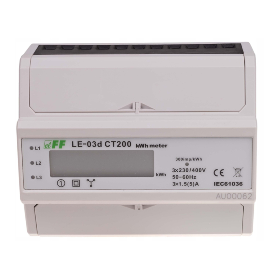
LE-03d CT200
Electric energy meter,
3-phase
Do not dispose of this device in the trash along with other waste!
According to the Law on Waste, electro coming from households free of charge and can
give any amount to up to that end point of collec� on, as well as to store the occasion of
the purchase of new equipment (in accordance with the principle of old-for-new, regard-
less of brand). Electro thrown in the trash or abandoned in nature, pose a threat to the
environment and human health.
Purpose
The LE-03d CT200 is a static (electronic) calibrated electricity
meter of three-phase alternating current in a semidirect system.
The meter is designed to work with current transformers with
a primary current of 200 A and a secondary current of 5 A. The
maximum measured current of the system is determined by the
value of the primary current of the current transformer used.
When using transformers with dedicated parameters, the meter
shows the actual value of electricity consumed by the system.
Functioning
A special electronic system under the influence of flowing cu-
rrent and applied voltage in each phase generates pulses pro-
portional to the energy drawn in the respective phase. Energy
consumption in the phase is indicated by a flashing of corre-
sponding LED (L1, L2, L3). The sum of the three phase pulses is
indicated by a flashing LED and converted into energy absorbed
throughout the three-phase system. Its value is displayed by the
segment LCD display.
F&F Filipowski sp. j.
Konstantynowska 79/81, 95-200 Pabianice, POLAND
phone/fax (+48 42) 215 23 83 / (+48 42) 227 09 71
www.fif.com.pl; e-mail: biuro@fif.com.pl
- 1 -
Advertisement
Table of Contents

Related Manuals for F&F LE-03d CT200


Summary of Contents for F&F LE-03d CT200
- Page 1 Electro thrown in the trash or abandoned in nature, pose a threat to the environment and human health. Purpose The LE-03d CT200 is a static (electronic) calibrated electricity meter of three-phase alternating current in a semidirect system. The meter is designed to work with current transformers with a primary current of 200 A and a secondary current of 5 A.
- Page 2 Pulse output The meter is equipped with pulse output open collector (OC type). This allows you to connect another pulse device (SO) that reads pulses generated by the meter. No additional connected equipment is required for proper ope- ration of the meter. Sealing The meter has sealable input and output terminal covers to pre- vent any attempts to bypass the meter.
- Page 3 Meter number The meter is marked with individual serial number allowing its unambiguous identification. The marking is laser engraved and cannot be removed). Front description - 3 -...
- Page 4 Dimensions Mounting 1. Disconnect the power supply. 2. The indicator mounted on a rail in the distribution box. 3. Connect the voltages of controlled phases to the terminals in accordance with the markings 18 (L1), 17 (L2), 16 (L3). 4. Connect the transformers to the phase conductors and con- nect the secondary outputs to the terminals in accordance with the markings 1-2 (L1), 3-4 (L2), 5-6 (L3).
- Page 5 Wiring diagram Current measurement circuits: L1 phase L2 phase L3 phase Pulse output (open collector): transistor emitter (–) transistor collector (+) cont. on next page - 5 -...
- Page 6 The circuit for measuring the voltage and supply of the meter: neutral N-wire L3 phase L2 phase L1 phase Technical data installation 4-wire rated voltage 3×230/400 V minimum measured current 0.04 A base current 3×1.5 A maximum current 3×5 A voltage measuring range 160÷265 V transformer type...
- Page 7 dimensions 7 modules (122 mm) mounting on TH-35 rail ingress protection IP20 Warranty F&F products are covered by a 24-month warranty from the date of purchase. The warranty is only valid with proof of purchase. Contact your dealer or contact us directly. CE declaration F&F Filipowski sp.
- Page 8 General work safety conditions » Please read the instructions carefully before installation. » The device should be installed and operated by qualified per- sonnel who are familiar with its design, operation, and asso- ciated risks. » Do not install a meter that is damaged or incomplete. »...
Need help?
Do you have a question about the LE-03d CT200 and is the answer not in the manual?
Questions and answers