
Related Manuals for Timberwolf PTO/300H


Summary of Contents for Timberwolf PTO/300H
-
Page 1: Table Of Contents
CONTENTS Section Page No. INTRODUCTION PURPOSE OF MACHINE MACHINE DIMENSIONS PARTS LOCATION DIAGRAMS 3 & 4 SAFE WORKING Operator’s Personal Protective Equipment Required Basic Woodchipping Safety General Safety Matters - Do’s and Dont’s Noise Test OPERATING INSTRUCTIONS Delivery Operator’s Personal Protective Equipment Required Hydraulic Oil Thermometer/Hydraulic Oil Lever Indicator Connecting to Tractor PTO Shaft... -
Page 2: Introduction
- damage to property - a member of the general public becoming injured This manual covers the operation and maintenance of the Timberwolf PTO/300H. All information in this manual is based on the latest product information available at the time. -
Page 3: Purpose Of Machine
TIMBERWOLF PTO/300H PURPOSE OF MACHINE The Timberwolf PTO/300H brushwood chipper is designed to chip solid wood material up to 300mm in diameter, depending on tractor horsepower. It is capable of chipping up to sixteen tonnes of brushwood per hour. DIMENSIONS... -
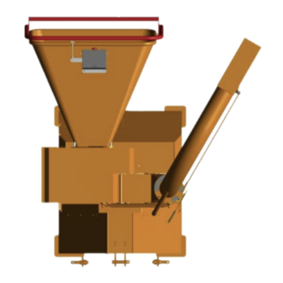
Page 4: Parts Location Diagrams 3
PARTS LOCATOR OPENING DISCHARGE DISCHARGE ROTOR BUCKET TUBE HOUSING OPEN SIDE TOP GUARD GUARD CONTROL BOX MOTOR SIDE GUARD SAFETY BAR FUNNEL LOWER SAFETY BAR ROTOR FRAME ROLLER BOX COVERS BELT GUARD... - Page 5 PARTS LOCATOR...
-
Page 6: Safe Working
SAFE WORKING WARNING The chipper will feed material through on its own. To do this, it relies on sharp blades on the chipper rotor. To keep the blades sharp, only feed the machine with clean brushwood. DO NOT put muddy/dirty wood, roots, potted plants, bricks, stones or metal into the chipper. -
Page 7: General Safety Matters - Do's And Dont's
SAFE WORKING GENERAL SAFETY MATTERS D O ’ S A N D D O N ’ T S ALWAYS stop the tractor engine and disconnect DO NOT use chipper unless available light is the PTO shaft before making any adjustments, sufficient to see clearly. -
Page 8: Noise Test
SAFE WORKING NOISE TEST MACHINE: TIMBERWOLF PTO/300H ATTACHED TO A JCB FASTRAK NOTES: TESTED CHIPPING 4 INCH ROUND POLES ALL READINGS REPRESENT TRACTOR WITH CHIPPER CHIPPING Noise levels between 85 and 113.3dBA will be experienced at the working position. Wear ear defenders at all times to prevent possible damage to hearing. -
Page 9: Operating Instructions
OPERATING INSTRUCTIONS DELIVERY All Timberwolf PTO/300H machines have a full pre delivery inspection before leaving the factory and are ready to use. Read and understand this instruction manual before attempting to operate the chipper. In particular, read pages 5-8 which contains important health and safety information and advice. -
Page 10: Daily Checks Before Starting Tractor
OPERATING INSTRUCTIONS DAILY CHECKS BEFORE STARTING TRACTOR ENSURE drive shaft ends are securely fitted to PTO shaft and implement input shaft. CHECK for properly guarded PTO shaft, implement input and drive shaft. CHECK that guard chains are securely attached to stationary frame to prevent rotation of guard. CONNECT power cable from tractor to chipper and turn on tractor side lights. -
Page 11: Manual Controls
OPERATING INSTRUCTIONS MANUAL CONTROLS Roller control box - is the control box above the feed opening of the chipper funnel. Its function is to control the feed rollers. The feed rollers draw material into the machine. It does not control the main rotor. RED SAFETY BAR = This is the large red bar that surrounds the feed funnel. -
Page 12: Discharge Controls
OPERATING INSTRUCTIONS DISCHARGE CONTROLS Controlling the discharge is an essential part of safe working. ROTATION Slacken nut using integral handle. Rotate tube using handles. Retighten nut. BUCKET ANGLE Adjust the bucket to the desired angle using the handle provided. STARTING THE CHIPPER WARNING Do not use or attempt to start the chipper without the protective guarding and discharge unit securely in place. -
Page 13: Stopping The Chipper
OPERATING INSTRUCTIONS STOPPING THE CHIPPER PUSH the RED STOP button (see control panel diagram on page 10). KEEPING PTO engaged set tractor speed to idle. WHEN idle speed steady stop tractor engine. WHEN engine stationary disengage PTO clutch. DO NOT disengage the PTO clutch while engine is running as the chipper cutting disc may continue to free wheel for a long time. -
Page 14: Service Instructions
MAINTENANCE THAT SHOULD BE APPLIED TO ANY PIECE OF MECHANICAL EQUIPMENT AND THE CHASSIS TO WHICH IT IS MOUNTED. AUTHORISED TIMBERWOLF SERVICE AGENTS ARE FULLY TRAINED IN ALL ASPECTS OF TOTAL SERVICE AND MAINTENANCE OF TIMBERWOLF WOODCHIPPERS. YOU ARE STRONGLY ADVISED TO TAKE YOUR CHIPPER TO AN AUTHORISED AGENT FOR ALL BUT THE MOST ROUTINE MAINTENANCE AND CHECKS. -
Page 15: Service Schedule
Inspect anvil and roller feed blades. Return to dealer for replacing or sharpening as appropriate. NOTE: Your Timberwolf woodchipper is covered by a full 12 months parts and labour warranty. Subject to correct maintenance and proper machine usage, the bearings are guaranteed for 12 months regardless of hours worked by the machine. -
Page 16: Safe Maintenance
SPARES Only fit genuine Timberwolf replacement blades, bolts and chipper spares. Failure to do so will result in the invalidation of the warranty and may result in damage to the chipper, personal injury or even loss of life. -
Page 17: Change Blades
SERVICE INSTRUCTIONS CHANGE BLADES WARNING Wear riggers gloves for the blade changing operation. Correct assembly Rotor housing in open position Rotate discharge chute across the machine Before refitting a blade to the rotor, the underside of the blade, the tapered bolt and clamp. -
Page 18: Sharpen The Roller Blades
2 - 3 hours and adjust until the tension remains constant. Belt failures due to lack of correct tensioning will not be covered under your Timberwolf warranty. NOTE: This is best done with the chipper removed from the tractor. -
Page 19: Change Hydraulic Oil And Filter
SERVICE INSTRUCTIONS CHANGE HYDRAULIC OIL AND FILTER WARNING Use plastic gloves to keep oil off skin and dispose of the used oil and filter in an ecologically sound way. The oil and filter should be changed once a year or at any time it becomes contaminated. Before starting check that the chipper is standing level and brush away loose chips. -
Page 20: Warranty Statement
– in these situations they are duly authorised to transfer any remaining warranty period to their first end user. Any warranty offered by the Timberwolf Dealer beyond the original 12 month period will be wholly covered by said Dealer. -
Page 21: Ec Declaration Of Incorporation Certificate
CERTIFICATE OF CONFORMITY... -
Page 22: Decals 21
DECALS DANGER DANGER HIGH DANGER VELOCITY TIMBERWOLF DISCHARGE DANGER DANGER KEEP CLEAR! DANGER DANGER DANGER 1136 1363 OPERATING INSTRUCTIONS READ THE INSTRUCTION MANUAL. THE INSTRUCTION MANUAL WITH THIS MACHINE P T O 3 0 0 H CONTAINS IMPORTANT OPERATING, MAINTENANCE AND HEALTH AND SAFETY INFORMATION. - Page 23 DECALS...
-
Page 24: Electrical Details
ELECTRICAL DETAILS Date Last Modified: 1st Feb 05... -
Page 25: Wiring Diagram
WIRING DIAGRAM... -
Page 26: Hydraulic Layout
HYDRAULIC LAYOUT FILTER 4123 TANK FILTER 4117 4119 PUMP 4118 4122 4120 MOTOR MOTOR 4121... -
Page 27: Parts Lists
TIMBERWOLF PTO/300H PARTS LISTS The following illustrations are for parts identification only. The removal or fitting of these parts may cause a hazard and should only be carried out by trained personnel. Page No. CONTROL BOX (UPPER SECTION) CONTROL BOX (LOWER SECTION) -
Page 28: Control Box (Upper Section)
CONTROL BOX (UPPER SECTION) Date Last Modified: 21st July 05 Item Part No Part Name Q’ty Item Part No Part Name Q’ty 2794FB Control Box Cover 2804 Bush M10 Top Hat 2803 M10/240 Bolt 2807 AV Mount 20 x 16 0839 M10 C Washer 0857... -
Page 29: Control Box (Lower Section)
CONTROL BOX (LOWER SECTION) Date Last Modified: 15th Dec 06 Item Part No Part Name Q’ty Item Part No Part Name Q’ty 18168 M4/35 Pan Pozi 1603 Spring 18100 M4 A Washer 18119 M8/70 Bolt 1692 Limit Switch 3055FB Link Mechanism Casing 18235 M4 P Nyloc Nut 0431... -
Page 30: Discharge
DISCHARGE Item Part No Part Name Q’ty 1521 M12/190 Bolt 0704 M12 C Washer 1813FO Discharge Bucket 0644 M12 P Nyloc Nut 1811FO Discharge Tube 1580 M10/60 Bolt 4344 Pivot Bush Washer 2236 Pivot Bush 0052 M10 T Nyloc Nut 2350S Control Link Arm 1687FS... -
Page 31: Drive Train
DRIVE TRAIN Date Last Modified: 23rd Oct 08 Item Part No Part Name Q’ty Item Part No Part Name Q’ty 18060MS PTO Adapter 18085 M12/40 Fine Caphead 1525 M10/40 Fine Caphead 0390 Belt SPA 1000 0346 M8/20 Bolt Top Hat Bush 0711 M8 A Washer 4125... -
Page 32: Electrical Layout
ELECTRICAL LAYOUT Item Part No Part Name Q’ty 3019 Main Loom 18419F No Stress Sensor Date Last Modified: 20th Dec 07 4113 Remote Sensor Loom... -
Page 33: Electrical Panel
ELECTRICAL PANEL Date Last Modified: 20th Dec 07 Item Part No Part Name Q’ty Item Part No Part Name Q’ty 17301 AV Mount 18107 M6 Wing Nut Relay 0438 M6/16 Pan Pozi supp’d with loom 4140 1921FS Electrical Plate 1151 Countersunk Pop Rivet 0709 M6 C Washer... -
Page 34: Frame
FRAME each side x2 each side Date Last Modified: 10th Nov 05 Item Part No Part Name Q’ty Item Part No Part Name Q’ty 1248FO Top Guard 4102FO Top Brace 1290FO Motor Side Guard 4112FO Low Funnel Support 1289FO Open Side Guard 0277 M12/25 Bolt 2401O... -
Page 35: Funnel
FUNNEL Date Last Modified: 10th Nov 05 Item Part No Part Name Q’ty Item Part No Part Name Q’ty Control Box 4116M Spacer Tube See pages 27/28 4069FO Funnel 1599 Bearing Washer 2989FR Safety Bar 4115FR Underslung Safety Bar 0431 M12/40 Bolt 1511 M16 P Nyloc Nut... -
Page 36: Hydraulics
HYDRAULICS 11 12 14 15 Date Last Modified: 2nd Jan 08 Item Part No Part Name Q’ty Item Part No Part Name Q’ty 1577 Motor 1766 3/4”- 3/4” m/m Adaptor 0398 1/2” Dowty Seal 4117 3/4” Hose, Pump to Hyd Tank 0027 1/2”... -
Page 37: Lubrication System
LUBRICATION SYSTEM Date Last Modified: 17th Jan 08 Item Part No Part Name Q’ty Item Part No Part Name Q’ty 2708 Y Piece 18430 Top Bearing Final Feed 1000mm 18430 Motor Side Slide Feed 1800mm 18430 Bearing Side Slide Feed 1150mm 18430 Slide Final Feed 270mm 18430... -
Page 38: Roller Box
ROLLER BOX Date Last Modified: 20th Dec 07 Item Part No Part Name Q’ty Item Part No Part Name Q’ty 1518 M12/130 Bolt 2214M Shaft Clamp Pair 2137P Top Brace Plate 1643 M16 Stud 2138MS Top Plate Pillar 1143 M16 Washer 0878 M10/20 Set Screw 1284... -
Page 39: Rotor
ROTOR Date Last Modified: 20th Nov 07 Item Part No Part Name Q’ty Item Part No Part Name Q’ty 2583MS Rotor Shaft 0348 M8/20 CSK Bolt 0351 M8/30 Capheads 2921MS Bolt Plate 2114MS Bearing Cap 4251M 4 Blade Rotor 2419 Rotor Bearing 6311 2RSC3 2156 Rotor Bearing 6310 2RSC3... -
Page 40: Rotor Housing
ROTOR HOUSING Date Last Modified: 20th Dec 07 Item Part No Part Name Q’ty Item Part No Part Name Q’ty 18413FO Fixed Rotor Housing 0839 M10 A Washer 18415FO Moving Rotor Housing 0714 M8 Penny Washer 0346 M8/20 Bolt 1217FS Catch Slide 0711 M8 A Washer... -
Page 41: V-Belt Tensioning Table
V-BELT TENSIONING TABLE...
Need help?
Do you have a question about the PTO/300H and is the answer not in the manual?
Questions and answers