
Subscribe to Our Youtube Channel
Related Manuals for Timberwolf PTO/150H


Summary of Contents for Timberwolf PTO/150H
-
Page 1: Table Of Contents
CONTENTS Section Page No. INTRODUCTION PURPOSE OF MACHINE MACHINE SPECIFICATIONS PARTS LOCATION DIAGRAMS 3 & 4 SAFE WORKING Operator’s Personal Protective Equipment Required Basic Woodchipping Safety General Safety Matters - Do’s and Don’ts Noise Test OPERATING INSTRUCTIONS Delivery Operator’s Personal Protective Equipment Required Hydraulic Oil Thermometer / Oil Lever Indicator Connecting to Tractor PTO Shaft... -
Page 2: Introduction
- damage to property - a member of the general public becoming injured This manual covers the operation and maintenance of the Timberwolf PTO/150H. All information in this manual is based on the latest product information available at the time. -
Page 3: Purpose Of Machine
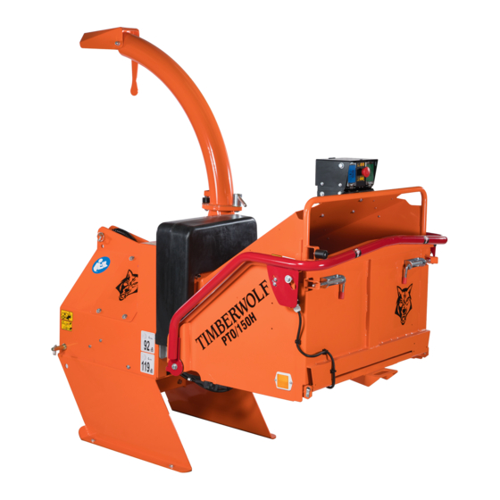
TIMBERWOLF PTO/150H PURPOSE OF MACHINE The Timberwolf PTO/150H brushwood chipper is designed to chip solid wood material up to 150 mm in diameter, depending on tractor horsepower. It is capable of chipping over three tonnes of brushwood per hour. DIMENSIONS... -
Page 4: Parts Location Diagrams 3
PARTS LOCATOR CONTROL BOX DISCHARGE BUCKET DISCHARGE TUBE DISCHARGE HANDLE ROLLER BOX COVER DISCHARGE CLAMPS SAFETY BAR FEED TRAY FUNNEL ROTOR HOUSING POWER CABLE SOCKET OIL TANK... - Page 5 PARTS LOCATOR MACHINE NO. PLATE FAN SECTION (X2) ROTOR NO STRESS SENSOR BREATHER PIPE ROTOR DRIVE PULLEY GEARBOX TANK TOP FILTER HYDRAULIC PUMP DIRECTIONAL CONTROL VALVE (DCV) CONNECTION OIL LEVEL GAUGE...
-
Page 6: Safe Working
SAFE WORKING WARNING The chipper will feed material through on its own. To do this, it relies on sharp blades on both on the infeed rollers and on the chipper rotor. To keep the blades sharp, only feed the machine with clean brushwood. DO NOT put muddy/dirty wood, roots, potted plants, bricks, stones or metal into the chipper. -
Page 7: General Safety Matters - Do's And Don'ts
SAFE WORKING GENERAL SAFETY MATTERS D O ’ S A N D D O N ’ T S ALWAYS stop the tractor engine and disconnect DO NOT use chipper unless available light is the PTO shaft before making any adjustments, sufficient to see clearly. -
Page 8: Noise Test
SAFE WORKING NOISE TEST MACHINE: TIMBERWOLF PTO/150H ATTACHED TO A 40HP TRACTOR NOTES: TESTED CHIPPING 4 INCH ROUND POLES ALL READINGS REPRESENT TRACTOR WITH CHIPPER CHIPPING Noise levels between 80 and 114dBA will be experienced at the working position. Wear ear defenders at all times to prevent possible damage to hearing. -
Page 9: Operating Instructions
OPERATING INSTRUCTIONS DELIVERY All Timberwolf PTO/150H machines have a full pre delivery inspection before leaving the factory and are ready to use. Read and understand this instruction manual before attempting to operate the chipper. In particular, read pages 5-8 which contains important health and safety information and advice. -
Page 10: Moving The Chipper
OPERATING INSTRUCTIONS MOVING THE CHIPPER DO NOT move the chipper with the rotor running. ALWAYS ensure the retaining nuts and clamp are tight when transporting with a discharge tube in place. NEVER pull the machine by the red safety bar as linkages will be damaged. DAILY CHECKS BEFORE STARTING TRACTOR ENSURE drive shaft ends are securely fitted to PTO shaft and chipper input shaft. -
Page 11: Manual Controls
OPERATING INSTRUCTIONS MANUAL CONTROLS Roller control box - is the control box above the feed opening of the chipper funnel. Its function is to control the feed rollers. The feed rollers draw material into the machine. It does not control the main rotor. RED SAFETY BAR = This is the large red bar that surrounds the feed tray and side of the feed funnel. -
Page 12: Emergency Stopping
OPERATING INSTRUCTIONS EMERGENCY STOPPING Push the RED STOP button or push the RED SAFETY BAR (whichever is the quickest for you to reach). Turn off tractor ignition key or operate tractor stop lever. The emergency stop will prevent any more material being fed into the chipper. The rotor will still be turning. -
Page 13: Stopping The Chipper
OPERATING INSTRUCTIONS STOPPING THE CHIPPER PUSH the RED STOP button (see control panel diagram, page 10). SHUT feed funnel. KEEPING PTO engaged set tractor speed to idle. WHEN idle speed steady stop tractor engine. WHEN engine stationary disengage PTO clutch. WARNING! DO NOT disengage the PTO clutch while engine is running as the chipper cutting disc may continue to free wheel for a long time. -
Page 14: Service Instructions
MAINTENANCE THAT SHOULD BE APPLIED TO ANY PIECE OF MECHANICAL EQUIPMENT AND THE CHASSIS TO WHICH IT IS MOUNTED. AUTHORISED TIMBERWOLF SERVICE AGENTS ARE FULLY TRAINED IN ALL ASPECTS OF TOTAL SERVICE AND MAINTENANCE OF TIMBERWOLF WOODCHIPPERS. YOU ARE STRONGLY ADVISED TO TAKE YOUR CHIPPER TO AN AUTHORISED AGENT FOR ALL BUT THE MOST ROUTINE MAINTENANCE AND CHECKS. -
Page 15: Service Schedule
Inspect anvil and roller feed blades. Return to dealer for replacing or sharpening as appropriate. NOTE: Your Timberwolf woodchipper is covered by a full 12 months parts and labour warranty. Subject to correct maintenance and proper machine usage, the bearings are guaranteed for 12 months regardless of hours worked by the machine. -
Page 16: Safe Maintenance
Tel: 01474 564311, Fax: 01474 333000. CHECK FITTINGS The Timberwolf PTO/150H is subject to large vibrations during the normal course of operation. Consequently there is always an possibility that nuts and bolts will work themselves loose. It is important that periodic checks are made to ensure the security of all fasteners. Fasteners should be tightened using a torque wrench to the settings listed below . -
Page 17: Change Blades
Note: This torque setting is vitally piece of wood to hold in place. important to ensure your bolts come out at a later date and Timberwolf recommend Remove blade access cover. you use a calibrated torque wrench for this and other jobs on the chipper. -
Page 18: Pto Drive Shaft Maintenance
SERVICE INSTRUCTIONS PTO DRIVE SHAFT MAINTENANCE Lubricate regularly. At least every 16 hours on coupling grease nipples and 8 hours on all other lubricated points. Replace prop shaft shear bolts only with correct grade of bolt available from the shaft supplier. SEE SEPARATE PROP SHAFT INSTRUCTION SHEET FOR FULL DETAILS. -
Page 19: Tension Belts
NOTE: There will normally be a rapid drop in tension during run-in period for new belts. When new belts are fitted, check the tension every 2 - 3 hours and adjust until the tension remains constant. Belt failures due to lack of correct tensioning will not be covered under your Timberwolf warranty. TENSION DRIVE BELTS Remove the belt guard. -
Page 20: Warranty Statement
– in these situations they are duly authorised to transfer any remaining warranty period to their first end user. Any warranty offered by the Timberwolf Dealer beyond the original 12 month period will be wholly covered by said Dealer. -
Page 21: Ec Declaration Of Incorporation Certificate
CERTIFICATE OF CONFORMITY... -
Page 22: Decals 21
!! ATTENTION !! WHEN RE-FITTING THS GUARD ENSURE THAT STEEL RETAINING BRACKET IS ON THE INSIDE DAMAGED GUARDS DUE TO INCORRECT ASSEMBLY WILL NOT BE COVERED BY YOUR TIMBERWOLF WARRANTY 18438 CHASSIS IDENTIFICATION PLATE (1294) Last Updated 18th Sept 08... - Page 23 DECALS 671 - these individual decals are supplied as a set, they may not all apply to your machine.
-
Page 24: Electrical Detail
ELECTRICAL DETAIL Date Last Modified: 3rd April 06... -
Page 25: Wiring Diagram
WIRING DIAGRAM... -
Page 26: Hydraulic Layout
HYDRAULIC LAYOUT 1822 TANK FILTER 1823 0381 PUMP 1302 0489 0475 MOTOR MOTOR 0323... -
Page 27: Parts Lists
TIMBERWOLF PTO/150H PARTS LISTS The following illustrations are for parts identification only. The removal or fitting of these parts may cause a hazard and should only be carried out by trained personnel. Page No. CONTROL BOX DECALS See pages 21 - 22... -
Page 28: Control Box
CONTROL BOX Date Last Modified: 21st July 04 Item Part No Part Name Q’ty Item Part No Part Name Q’ty 2794FB Control Box Cover 0857 M5 A Washer 2803 M10/240 Bolt 18103 M5/8 Pan Pozi 0839 M10 C Washer 18168 M4/35 Pan Pozi 4345 M10 P Nyloc Nut... -
Page 29: Discharge / Frame
DISCHARGE / FRAME Date Last Modified: 24th Jan 08 Item Part No Part Name Q’ty Item Part No Part Name Q’ty 0904FO Discharge Tube 0943 Top Pin 0523FO Discharge Bucket 0430 M12/35 Cup Square 0045 M12 T Nyloc Nut 0236 M5 P Nyloc Nut 0702 M12 A Washer... -
Page 30: Drive Train
DRIVE TRAIN Date Last Modified: 10th Sept 09 Item Part No Part Name Q’ty Item Part No Part Name Q’ty 0994 Belt 0701 M10 A Washer 0949M Pulley 140 x 1 SPA 0878 M10/20 Bolt 1923S Trigger 0704 M12 C Washer 0437 M6/16 Bolt 0644... -
Page 31: Electrical Control Panel
ELECTRICAL CONTROL PANEL Date Last Modified: 13th March 06 Item Part No Part Name Q’ty Item Part No Part Name Q’ty 4033 AV Mount 18107 M6 Wing Nut Relay 0438 M6/16 Pan Pozi supp’d with loom 4140 1921FS Electrical Plate 1151 Countersunk Pop Rivet 0709... -
Page 32: Electrical Layout
ELECTRICAL LAYOUT Date Last Modified: 3rd Dec 08 Item Part No Part Name Q’ty Item Part No Part Name Q’ty 1975 Control Box Loom 4140 Main Loom 1406 Limit Switch Loom 1902 No Stress Sensor... -
Page 33: Funnel
FUNNEL Date Last Modified: 9th Oct 08 Item Part No Part Name Q’ty Item Part No Part Name Q’ty 2809F Control Box (see pg. 27) 1599 Bearing Washer 1721 M8/10 Bolt 1570FR Safety Bar 0654 Blank Grommet 1348 Limit Switch 4345 M10 P Nyloc Nut 1812... -
Page 34: Hydraulics
HYDRAULICS Date Last Modified: 30th Jan 08 Item Part No Part Name Q’ty Item Part No Part Name Q’ty 1434 Tank Top Filter Housing 1583 Adapter mm 1/2”- 3/4” BSP 0100 Filter 1823 Hose 3/4” Pump to Tank 0152 Washer Dowty 3/4” 0827 Adapter 3/4”... -
Page 35: Roller Box
ROLLER BOX Date Last Modified: 8th May 07 Item Part No Part Name Q’ty Item Part No Part Name Q’ty 0672 Rollerbox Cover 0985 Straight Grease Nipple 4340 M12/50 Caphead 0986 Grease Nipple 0481 M8 T Nyloc Nut 0055 Bearing Boss 18027M Plate Top Damper Carrier 0788... -
Page 36: Rotor
ROTOR Date Last Modified: 10th Sept 09 Item Part No Part Name Q’ty Item Part No Part Name Q’ty 0959 Plastic Cap 083MH Cutter Blade 4” 0884MS Bearing Housing Front 18275M Blade Pocket 18479K Rotor Nose Shaft Kit 0386 M10/30 Cap Screw 0880M Rotor 1571... -
Page 37: V-Belt Tensioning Table
V-BELT TENSIONING TABLE...
Need help?
Do you have a question about the PTO/150H and is the answer not in the manual?
Questions and answers