Chapters
Table of Contents

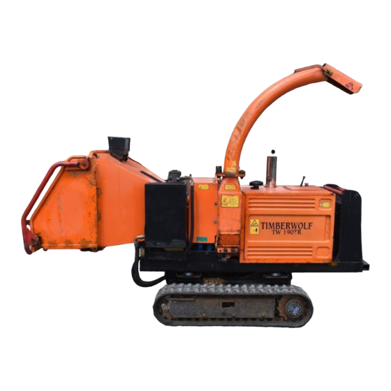
Related Manuals for Timberwolf TW 190TR TURBO VORTE


Summary of Contents for Timberwolf TW 190TR TURBO VORTE
-
Page 1: Table Of Contents
CONTENTS Section Page No. INTRODUCTION PURPOSE OF MACHINE MACHINE DIMENSIONS & SPECIFICATIONS PARTS LOCATION DIAGRAMS 3 & 4 SAFE WORKING Operator’s Personal Protective Equipment Required Basic Woodchipping Safety General Safety Matters - Do’s and Dont’s Noise Test OPERATING INSTRUCTIONS Delivery Operator’s Personal Protective Equipment Required Manual Controls Crawler Track Controls... -
Page 2: Introduction
Timberwolf's policy of constantly improving their products may involve major or minor changes to the chippers or their accessories. Timberwolf reserves the right to make changes at any time without notice and without incurring any obligation. -
Page 3: Purpose Of Machine
TIMBERWOLF 190TR TURBO VORTEX PURPOSE OF MACHINE The Timberwolf TW 190TR brushwood chipper is designed to chip solid wood TURBO VORTEX material up to 190 mm in diameter. The maximum cross-section hardwood for continuous feed is 28500 mm . It is capable of chipping up to 6.5 tonnes of brushwood per hour. -
Page 4: Parts Location Diagrams 3
PARTS LOCATOR DISCHARGE ROLLER DISCHARGE HYDRAULIC OIL TUBE CONTROLS BUCKET FILTER FEED FUNNEL LIFTING SAFETY BAR AIR INTAKE THROTTLE EMERGENCY STOP ENGINE GUARDS FEED TRAY DISCHARGE ADJUSTMENT CONTROL HYDRAULIC OIL TANK DRIVING ROTOR CRAWLER CONTROLS HOUSING TRACKS... - Page 5 PARTS LOCATOR EXHAUST AIR FILTER CUTTING BLADES ROTOR ROLLER BOX BATTERY TOP ROLLER SLIDE FUEL TANK FUEL FILTER FUEL PUMP IN-LINE FUEL FILTER HYDRAULIC PUMP RESERVE TANK STICK ROTOR PULLEY OIL FILTER DIRECTIONAL STARTER ENGINE CONTROL MOTOR DRIVE PULLEY CONTROL PANEL ALTERNATOR VALVE...
-
Page 6: Safe Working
SAFE WORKING WARNING The chipper will feed material through on its own. To do this, it relies on sharp blades on the chipper rotor. To keep the blades sharp, only feed the machine with clean brushwood. DO NOT put muddy/dirty wood, roots, potted plants, bricks, stones or metal into the chipper. -
Page 7: General Safety Matters - Do's And Dont's
SAFE WORKING GENERAL SAFETY MATTERS D O ’ S A N D D O N ’ T S ALWAYS stop the chipper engine before making DO NOT use chipper unless available light is any adjustments, refuelling or cleaning. sufficient to see clearly. ALWAYS check machine has stopped rotating DO NOT... -
Page 8: Noise Test
SAFE WORKING NOISE TEST MACHINE: 190TR TURBO VORTEX NOTES: Tested Chipping 120 mm x 120 mm Corsican Pine 1.5m in length Noise levels above 85dB (A) will be experienced at the working position. Wear ear protection at all times to prevent possible damage to hearing. All persons within a 4 metre radius must also wear good quality ear protection. -
Page 9: Operating Instructions
OPERATING INSTRUCTIONS DELIVERY All Timberwolf 190TR machines have a full pre - delivery inspection before leaving the TURBO VORTEX factory and are ready to use. Read and understand this instruction manual before attempting to operate the chipper. In particular, read pages 5-7 which contain important health and safety information and advice. -
Page 10: Crawler Track Controls
OPERATING INSTRUCTIONS CRAWLER TRACK CONTROLS WARNING NEVER LEAVE CHIPPER ON A SLOPE UNATTENDED. The chipper is designed to operate in either chipper or crawler mode, but not both at the same time. CHIPPING MODE Power is available to the feed rollers. The cutting disc is rotating but the unit is stationary. CRAWLER TRACK MODE Power is available to the crawler tracks. -
Page 11: Daily Checks Before Starting
OPERATING INSTRUCTIONS DAILY CHECKS BEFORE STARTING LOCATE the machine on firm level ground. CHECK machine is well supported and cannot move. CHECK all guards are fitted and secure. CHECK the discharge unit is in place and fastened securely. CHECK discharge tube is pointing in a safe direction. CHECK the feed funnel to ensure no objects are inside. -
Page 12: Before Using The Chipper
OPERATING INSTRUCTIONS BEFORE USING THE CHIPPER IT IS ESSENTIAL TO CARRY OUT THE FOLLOWING TESTS to check safety equipment - this sequence of tests will only take a few seconds to carry out. We recommend that these tests are carried out daily. -
Page 13: Hydraulic Oil Thermometer / Oil Level Indicator
OPERATING INSTRUCTIONS HYDRAULIC OIL THERMOMETER / OIL LEVEL INDICATOR This is situated on the side of the hydraulic oil tank. When the chipper is running, the oil temperature should not exceed 65 C. If it does, stop the machine immediately. Failure to do so may result in damage. Overheating can result from the chipper being worked extremely hard in hot conditions, as the oil is not getting a chance to cool down. -
Page 14: Service Instructions
MAINTENANCE THAT SHOULD BE APPLIED TO ANY PIECE OF MECHANICAL EQUIPMENT AND THE CHASSIS TO WHICH IT IS MOUNTED. AUTHORISED TIMBERWOLF SERVICE AGENTS ARE FULLY TRAINED IN ALL ASPECTS OF TOTAL SERVICE AND MAINTENANCE OF TIMBERWOLF WOODCHIPPERS. YOU ARE STRONGLY ADVISED TO TAKE YOUR CHIPPER TO AN AUTHORISED AGENT FOR ALL BUT THE MOST ROUTINE MAINTENANCE AND CHECKS. -
Page 15: Service Schedule
RETURN TO DEALER - 1500 HRS OR 3 YRS Replace anvils. NOTE: Your Timberwolf woodchipper is covered by a full 12 months parts and labour warranty. Subject to correct maintenance and proper machine usage, the bearings are guaranteed for 12 months regardless of hours worked by the machine. -
Page 16: Safe Maintenance
Inspect the lifting eye prior to each use - DO NOT USE LIFTING EYE IF DAMAGED. SPARES Only fit genuine Timberwolf replacement blades, screws and chipper spares. Failure to do so will result in the invalidation of the warranty and may result in damage to the chipper, personal injury or even loss of life. -
Page 17: Copper Ease Safety Information
SERVICE INSTRUCTIONS COPPER EASE SAFETY INFORMATION Product name: Copper Ease. Copper Ease contains no hazardous ingredients at or above regulatory disclosure limits, however, safety precautions should be taken when handling (use of oil-resistant gloves and saftey glasses are recommended - respiratory protection is not required). Avoid direct contact with the substance and store in a cool, well ventilated area avoiding sources of ignition, strong oxidising agents and strong acids. - Page 18 SERVICE INSTRUCTIONS BATTERY SAFETY INFORMATION...cont. 1. Storage and transport the positive output of the charger. Connect the - Batteries are filled with acid. negative terminal accordingly. - Always store and transport batteries upright - Switch on the charger only after the battery has and prevent from tilting so that no acid can been connected, and switch off the charger first escape.
-
Page 19: Change Blades
SERVICE INSTRUCTIONS CHANGE BLADES WARNING Wear heavy gloves for the blade changing operation. Correct assembly THIS PROCEDURE SHOULD ONLY BE UNDERTAKEN WITH THE DISCHARGE IN PLACE. Turn off the chipper and remove the key. reseating blades. The blades must not have any material underneath them Remove the negative battery lead. -
Page 20: Check Fittings
Open the rotor housing. tension & correct belt tension values, please Remove off side engine guard panel. refer to the Timberwolf V-Belt Tensioning Data Slacken the four 24 mm nuts that retain the Table (this information can be obtained from roller box (bolt is retained underneath). -
Page 21: Tension Hydraulic Pump Belt
Pivot pump assembly up or down to achieve the correct belt tension. For instructions on checking belt tension & correct belt tension values, please refer to the Timberwolf V-Belt Tensioning Data Table (this information can be obtained from your dealer). Hold assembly at this position while tightening the three M8 nuts and bolts. -
Page 22: Track Base Maintenance-Safe Maintenance
SERVICE INSTRUCTIONS TRACK BASE MAINTENANCE SAFE MAINTENANCE Solidly support the under carriage if it needs to be lifted up for maintenance. Hydraulic systems may get very hot after working. Keep all components in good condition as they are exposed to high pressures. Immediately repair damage and replace worn or broken items. -
Page 23: Checking Track Tension
SERVICE INSTRUCTIONS CHECKING TRACK TENSION Stop your machine on a flat and solid surface. Lift it in safe conditions and put stable supports under the undercarriage frame to properly support it. Measure distance A at the central roller of the undercarriage from the bottom of the roller to the rigid inside surface of the rubber track. -
Page 24: Checking The Rubber Tracks
SERVICE INSTRUCTIONS CHECKING THE RUBBER TRACKS CARVED PROFILE The structure of the rubber track is shown in this diagram. The steel cables (1) and metal core (2) are embedded in the rubber. There are many ways in which rubber tracks may be damaged. Some of these are terminal for the tracks, others are only cosmetic. -
Page 25: Removing The Rubber Tracks
SERVICE INSTRUCTIONS REMOVING THE RUBBER TRACKS Remove gravel or mud when they are jammed between the sprocket and the track link before loosening the track. Stop your machine on a solid and level surface. Lift it up and support it in safe conditions. Remove the screws and take off the cover that gives access to the adjustment system (Fig. -
Page 26: Warranty Statement
– in these situations they are duly authorised to transfer any remaining warranty period to their first end user. Any warranty offered by the Timberwolf Dealer beyond the original 12 month period will be wholly covered by said Dealer. -
Page 27: Ec Declaration Of Conformity Certificate
CERTIFICATE OF CONFORMITY... -
Page 28: Identification Plates
IDENTIFICATION PLATES CE PLATE CHASSIS IDENTIFICATION PLATE... - Page 29 READ THE INSTRUCTION MANUAL. THE INSTRUCTION MANUAL WITH THIS MACHINE CONTAINS IMPORTANT OPERATING, MAINTENANCE AND HEALTH AND SAFETY INFORMATION. FAILURE TO FOLLOW THE INFORMATION CONTAINED IN THE TIMBERWOLF INSTRUCTION MANUAL MAY LEAD TO DEATH OR SERIOUS INJURY. 1136 1662 2800...
-
Page 30: Decals 28
DECALS... -
Page 31: Electrical Details
ELECTRICAL DETAIL Date Last Modified: 12th May 06... -
Page 32: Hydraulic Layout
HYDRAULIC LAYOUT KIT NO: 4288 NEARSIDE OFFSIDE MOTOR MOTOR TRACK MOTORS 4346 4348 2867 4347 ROLLER OFF SIDE NEAR SIDE MOTORS PROPORTIONAL PROPORTIONAL 2874 3095 2877 2882 3096 2875 4240 2873 2885 2883 6 WAY DIVERTER 4000 MANIFOLD 3099 NEARSIDE OFFSIDE PUMP PUMP... -
Page 33: Circuit Diagram
CIRCUIT DIAGRAM Date Last Modified: 12th July 05... - Page 34 (blank)
-
Page 35: Parts Lists
T T I I M M B B E E R R W W O O L L F F T T I I M M B B E E R R W W O O L L F F T T W W 1 1 9 9 0 0 T T R R T T W W 1 1 9 9 0 0 T T R R URBO VORTEX... -
Page 36: Chassis
CHASSIS Date Last Modified: 8th June 07 Item Part No Part Name Q’ty Item Part No Part Name Q’ty 2905FB Roller Box Mounting Brkt 1628 M16/35 Bolt 2903FB Funnel Support 1143 M16 A Washer 0382 M10/30 Bolt 4067 D Rubber Fixing Plate 0702 M12 A Washer 0704... -
Page 37: Control Box
CONTROL BOX Date Last Modified: 21st July 05 Item Part No Part Name Q’ty Item Part No Part Name Q’ty 2794FB Control Box Cover 0857 M5 A Washer 2803 M10/240 Bolt 18103 M5/8 Pan Pozi 0839 M10 C Washer 18168 M4/35 Pan Pozi 4345 M10 P Nyloc Nut... -
Page 38: Control Panel
CONTROL PANEL Date Last Modified: 25th July 05 Item Part No Part Name Q’ty Item Part No Part Name Q’ty 18107 M6 Wing Nut 4033 M5 AV Mount 18106 M6 Split Washer Supp’d with loom 0709 M6 C Washer Ignition Switch Supp’d with engine 1972 Electrical Cover... -
Page 39: Control Tower
CONTROL TOWER 18 20 Date Last Modified: 24th Jan 07 Item Part No Part Name Q’ty Item Part No Part Name Q’ty 1802FR Cross Bar 1860 M8 Lever 1879FB Control Panel Tracked 1737 M8 Lever 1658 M6/12 Bolt 1738 Six Way Diverter Valve 0709 M6 C Washer 0354... -
Page 40: Discharge
DISCHARGE Item Part No Part Name Q’ty 0904FO Discharge Tube 0523FO Discharge Bucket 0644 M12 P Nyloc Nut 0702 M12 A Washer 0320 M12/25 Cup Square 0430 M12/35 Cup Square 0134 Black Handle Grip 1649MS Discharge Clamp Handle 4109M M16 Clamp Nut 4131 Roll Pin 0434... -
Page 41: Drive Train
DRIVE TRAIN Item Part No Part Name Q’ty 17322 Vee Belt 1232 XPA 4327 Taper Lock Bush 3020 50 mm 17321 Pulley 280 x 3 2984M Key 54 x 14 17314 Pulley Engine 168 x 4 17373 Vee Belt XPA 925 2975 Taper Lock Bush 1610 18 mm Date Last Modified: 23rd Jan 06... -
Page 42: Electrical Layout
ELECTRICAL LAYOUT Date Last Modified: 29th June 05 Item Part No Part Name Q’ty Item Part No Part Name Q’ty 1406 Safety Switch Loom 2627 Emergency Stop Switch - VE Battery Cable 1975 Control Box Loom 1376 + VE Battery Cable 2985 Engine Loom 1375... -
Page 43: Engine
ENGINE Date Last Modified: 10th May 07 Item Part No Part Name Q’ty Item Part No Part Name Q’ty 4316 Air Cleaner 0346 M8/20 Bolt 0095 Oil Filter 4297FB Air Intake Tube Air Filter 0304 M10/25 Fine Thread Socket Cap 16 4252 Directional Control Valve (DCV) 0085... -
Page 44: Engine Bay
ENGINE BAY Date Last Modified: 15th May 07 23 26 15 17 each side Item Part No Part Name Q’ty Item Part No Part Name Q’ty 2950 Throttle Decal 4318 Exhaust & Fittings 4299 Exhaust Deflector 4269FO Front Engine Bay Guard 4312 Exhaust Clamp 0235... -
Page 45: Fuel Tank
FUEL TANK Date Last Modified: 27th July 05 Item Part No Part Name Q’ty Item Part No Part Name Q’ty 1374 Locking Tank Cap 0211 3/8 Drain Plug 1658 M6/12 Bolt 2897M Pick Up Weight 0709 M6 C Washer 2896 Copper Washer 2920FS Fuel Tank Filler Assy... -
Page 46: Funnel
FUNNEL 10 22 Date Last Modified: 22nd Dec 05 Item Part No Part Name Q’ty Item Part No Part Name Q’ty 2809F Control Box 1348 Limit Switch (detail on page 36) 2913FO Funnel 1520 M10/45 Bolt 0045 M12 T Nyloc Nut 1591 Nylon Spacer 2914FO... -
Page 47: Hydraulics - Top
HYDRAULICS (TOP) 13 14 Date Last Modified: 2nd Sept 05 Item Part No Part Name Q’ty Item Part No Part Name Q’ty 3096 1/2” Hose, N/S 6-Way Valve 2867 1/2” Hose, O/S Track Bottom Motor 1 3095 1/2” Hose, O/S 6-Way Valve 2873 1/2”... -
Page 48: Hydraulics - Centre
HYDRAULICS (CENTRE) 11 12 Date Last Modified: 22nd March 07 Item Part No Part Name Q’ty Item Part No Part Name Q’ty 4000 1/2” Hose, Pump to 6-Way Valve 0027 1/2” - 1/2” M/M Adapter 3099 1/2” Hose, Pump to 6-Way Valve 0398 1/2”... -
Page 49: Hydraulics - End
HYDRAULICS (END) Date Last Modified: 7th Nov 05 Item Part No Part Name Q’ty Item Part No Part Name Q’ty 2884 3/4” Hose, Main Return 1702FS Tank Top Plate 4259 1” Hose, Tank Main Feed 0152 3/4” Dowty Seal 2873 1/2”... -
Page 50: Roller Box
ROLLER BOX... -
Page 51: Rotor
ROTOR Date Last Modified: 11th Sept 07... -
Page 52: Rotor Housing
ROTOR HOUSING Date Last Modified: 21st July 05 Item Part No Part Name Q’ty Item Part No Part Name Q’ty 1906FO Guard Roller Box Near Side 1 0178 Rubber End Stop 0878 M10/20 Bolt 0479 M8 P Nyloc Nut 0360 M10/25 Bolt 0712 M8 C Washer...
Need help?
Do you have a question about the TW 190TR TURBO VORTE and is the answer not in the manual?
Questions and answers