
Related Manuals for Vertiv NetSure V200E50


Summary of Contents for Vertiv NetSure V200E50
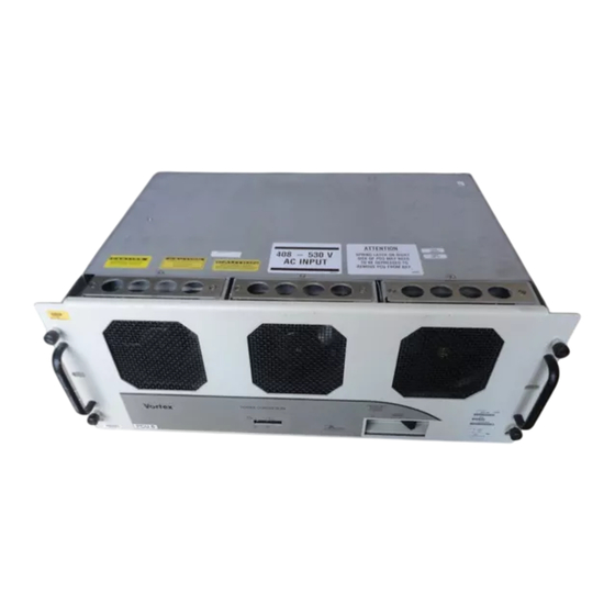
- Page 1 NetSure™ V200E50 DC Power Retrofit Installation and User Manual Specification Number: 486531003 Model Number: V200E50...
- Page 2 The information contained in this document is subject to change without notice and may not be suitable for all applications. While every precaution has been taken to ensure the accuracy and completeness of this document, Vertiv assumes no responsibility and disclaims all liability for damages resulting from use of this information or for any errors or omissions.
-
Page 3: Table Of Contents
Vertiv™ NetSure™ V200E50 DC Power Retrofit Installation and User Manual TABLE OF CONTENTS Admonishments Used in this Document ..........................iv Important Safety Instructions ..............................v Safety Admonishments Definitions ............................................v Safety and Regulatory Statements ............................................v Déclarations de Sécurité et de Réglementation ......................................v 1 Introduction ....................................1... -
Page 4: Admonishments Used In This Document
Vertiv™ NetSure™ V200E50 DC Power Retrofit Installation and User Manual Admonishments Used in this Document will likely DANGER! Warns of a hazard the reader be exposed to that will result in death or serious injury if not avoided. (ANSI, OSHA) -
Page 5: Important Safety Instructions
Vertiv™ NetSure™ V200E50 DC Power Retrofit Installation and User Manual Important Safety Instructions Safety Admonishments Definitions Definitions of the safety admonishments used in this document are listed under “Admonishments Used in this Document” on page iv. Safety and Regulatory Statements Refer to Section 4154 (provided with your customer documentation) for Safety and Regulatory Statements. - Page 6 Vertiv™ NetSure™ V200E50 DC Power Retrofit Installation and User Manual This page intentionally left blank. Proprietary and Confidential © 2022 Vertiv Group Corp.
-
Page 7: Introduction
1.1 General The Vertiv™ NetSure™ Model V200E50 DC Power Retrofit is a power solution comprising a Mounting Frame that allows two (2) new- generation NetSure Rectifiers (Model R48-5800e, Spec. No. 1R485800e), to be installed in the NetSure Model 1231V1, Spec. No. -
Page 8: Specifications
Vertiv™ NetSure™ V200E50 DC Power Retrofit Installation and User Manual 2 Specifications 2.1 DC Output Ratings Voltage: Nominal -48 volts DC, Positive Ground. Without Battery Charge Temperature Compensation: Float voltage is adjustable from 47.00 to 58.00 volts DC. Test/equalize voltage is adjustable from 45.00 to 58.00 volts DC. Adjustment is made via the system MCA. Refer to System Application Guide SAG582121300 for factory settings of Float and Test/Equalize voltages. - Page 9 Vertiv™ NetSure™ V200E50 DC Power Retrofit Installation and User Manual Power Derating Based on Input Voltage: See Figure 2.2. Figure 2.2 Output Power vs. Input Voltage Output Power vs. Input Voltage at Tamb < 45 C 250 275 300 325 350 375 400 425 450 475 500 525 550...
-
Page 10: Ac Input Ratings
Vertiv™ NetSure™ V200E50 DC Power Retrofit Installation and User Manual Filtering (with or without battery): Typical readings were taken at nominal input voltage, nominal output voltage, 50% load, and 25°C ambient. Voice Band Noise: Complies with Telcordia GR-947-CORE. Typically 17.68 dBrn C-message weighting. Does not exceed 32 dBrn C. - Page 11 Vertiv™ NetSure™ V200E50 DC Power Retrofit Installation and User Manual Typical Input Data: One (1) V200E50 Retrofit, 60 Hz input. System output is initially adjusted to 54.48 volts DC as measured at the system sense point at 50% of full load and nominal input.
-
Page 12: Environmental Ratings
Vertiv™ NetSure™ V200E50 DC Power Retrofit Installation and User Manual Typical Efficiency versus Output Current: See Figure 2.3. Figure 2.3 Typical Efficiency 97.0 96.0 95.0 94.0 93.0 92.0 91.0 90.0 89.0 88.0 87.0 2.3 Environmental Ratings Operating Ambient Temperature Range: Operational: -40°C to +65°C (-40°F to +149°F) -
Page 13: Standard Features
Vertiv™ NetSure™ V200E50 DC Power Retrofit Installation and User Manual NOTE! This level of protection is a widely used standard for telecommunications power equipment. As with all such equipment, it is the end user's responsibility to provide an adequately sized Surge Suppression Device at the commercial power service entrance of the building that reduces all incoming surges to levels below the classes/categories stated for the equipment. - Page 14 Vertiv™ NetSure™ V200E50 DC Power Retrofit Installation and User Manual Thermal Power Limiting: Each rectifier continuously monitors the ambient temperature surrounding the power conversion circuit. If this temperature for any reason (such as a high ambient temperature) increases above approximately +45°C (+113°F), the Rectifier will not shut down.
- Page 15 Vertiv™ NetSure™ V200E50 DC Power Retrofit Installation and User Manual Backup: If rectifier output voltage exceeds a second (non-adjustable) value, the rectifier shuts down and locks out regardless of load. Manual restart is then required. The backup HVSD setpoint is 59.5V (within the range of 58.5 to 60V).
-
Page 16: Installation
The Vertiv™ NetSure™ Model V200E50 DC Power Retrofit is designed to mount in a Model 1231V1, Spec. No. 582121300 Power Bay. Installation in any other Power System should not be attempted. -
Page 17: Remove Style Strips From Power Bay
Vertiv™ NetSure™ V200E50 DC Power Retrofit Installation and User Manual To return to the beginning of the MCA Logic Tree, press and release the FUNCTION SET YES (+) and NO (-) pushbuttons simultaneously. 3.3 Remove Style Strips from Power Bay Procedure Remove the two style strips from the front left and right edges of the VPS Power Bay being upgraded. -
Page 18: Install The Mounting Frame
Vertiv™ NetSure™ V200E50 DC Power Retrofit Installation and User Manual NOTE! In the next step, a safety latch is present on each PCU that prevents the PCU from inadvertently being removed completely from the Power Bay. Loosen the captive fasteners on the front of the PCU to be removed. Use the handles provided on the front of the PCU, and pull the PCU out until it is stopped by a safety latch located on the right-hand side panel of the PCU. - Page 19 Vertiv™ NetSure™ V200E50 DC Power Retrofit Installation and User Manual Figure 3.3 Identifying Older Style Bays Spring Newer Style Bays Have the Springs, Older Style Bays Do Not Have Springs Rectifier AC/Data Connector Spring Proprietary and Confidential © 2022 Vertiv Group Corp.
- Page 20 Vertiv™ NetSure™ V200E50 DC Power Retrofit Installation and User Manual Check Procedure (Older Style Bays Only) With the PCU removed, use a quality wooden carpenter’s ruler or other non-conductive rule. Place the measuring device directly against the unpainted bracket holding the AC/Data connector. Take two measurements, one on the bottom of connector directly next to the bolt through the black ac housing, and note the distance to the front outside of the left side panel.
- Page 21 Vertiv™ NetSure™ V200E50 DC Power Retrofit Installation and User Manual Figure 3.5 Locating the Bottom Two 1/4” Self Tapping Screws and 1/4” Hex Bolt Loosen These Next loosen the two Philips 1/4” self tapping screws at the top of the PCU position to be adjusted. See Figure 3.6.
-
Page 22: Install The Rectifiers
Vertiv™ NetSure™ V200E50 DC Power Retrofit Installation and User Manual Mounting Procedure Remove the front cover panel from the Mounting Frame by first loosening two captive fasteners. Refer to Figure 3.7. Figure 3.7 Removing the Cover Panel from the Mounting Frame... - Page 23 Vertiv™ NetSure™ V200E50 DC Power Retrofit Installation and User Manual Figure 3.8 Rectifier Handle and Safety Latch Handle Captive Safety Fastener Safety Latch Latch Release Handle Gently push the Rectifier into the Mounting Frame until it stops. Note that the Rectifier will NOT be completely seated in the Mounting Frame until the next step is performed.
-
Page 24: Install Remaining Retrofits In Power Bay
Vertiv™ NetSure™ V200E50 DC Power Retrofit Installation and User Manual Figure 3.9 Securing Front Cover Panel (2) R48-5800 Rectifiers Installed Mounting Frame Front Cover Panel Captive Fasteners 3.7 Install Remaining Retrofits in Power Bay Repeat the installation procedure for each V200 Retrofit remaining to be installed in the Power Bay. -
Page 25: Local Sense
Vertiv™ NetSure™ V200E50 DC Power Retrofit Installation and User Manual Press and release the FUNCTION SET YES (+) and NO (-) pushbuttons simultaneously, to return to the beginning of the MCA menu tree. 3.11 Local Sense If the system is wired for remote sense, it is recommended to switch to local sense as follows. - Page 26 Vertiv™ NetSure™ V200E50 DC Power Retrofit Installation and User Manual Figure 3.10 VPS Power Bay to MCA Interface Circuit Card 509962 -SNS +SNS "VPS POWER BAY TO MCA INTERFACE" CIRCUIT CARD 509962 REAR VIEW OF 1st VPS POWER BAY Proprietary and Confidential © 2022 Vertiv Group Corp.
-
Page 27: Operation
Vertiv™ NetSure™ V200E50 DC Power Retrofit Installation and User Manual 4 Operation 4.1 Local Indicators Four indicators are located on the front panel of each rectifier in the V200 Retrofit. The functions of these indicators are as shown in Table 4.1. Refer to Figure 4.1 for the location and identification of the local indicators. -
Page 28: Rectifier High Voltage Shutdown And Lockout Restart
Vertiv™ NetSure™ V200E50 DC Power Retrofit Installation and User Manual Table 4.1 Local Indicators Normal Fault Indicator Fault Cause State State No input voltage. Power (Green) Internal input fuse open. AC input under/over voltage. PFC output under/over voltage. Protection High temperature. - Page 29 Vertiv™ NetSure™ V200E50 DC Power Retrofit Installation and User Manual The fault indicators that each Rectifier can display are as follows: Power indicator (green) OFF, Protection indicator (yellow) ON or FLASHING, and Alarm indicator (red) ON or FLASHING. Refer to Table 5.1 for a list of possible causes and corrective actions.
-
Page 30: Replacement Procedures
Vertiv™ NetSure™ V200E50 DC Power Retrofit Installation and User Manual 5.2 Replacement Procedures 5.2.1 Replacing a Rectifier DANGER! Use caution when removing a Rectifier that has been operating, as Rectifier surfaces could be very hot. WARNING! In order to prevent damage to the latching mechanism, do not use excessive force on the Rectifier handle when pushing the Rectifier into the Mounting Frame. - Page 31 Vertiv™ NetSure™ V200E50 DC Power Retrofit Installation and User Manual CAUTION! When performing any step in this procedure that requires removal or installation of hardware, use caution to ensure no hardware is dropped and left inside the cabinet; otherwise service interruption or equipment damage may occur.
- Page 32 Vertiv™ NetSure™ V200E50 DC Power Retrofit Installation and User Manual Figure 5.1 Replacing the Rectifier Interface Circuit Card Top Cover Interface Circuit Card P/N 547568 Disconnect two (2) cables from the interface circuit card. Remove the one screw that secures the circuit card. Carefully lift the circuit card from its mounting posts, and remove.
-
Page 33: Replacing A Fan In A Rectifier
Vertiv™ NetSure™ V200E50 DC Power Retrofit Installation and User Manual Ensure that there are no local or remote alarms active on the system. Install the front cover on the Mounting Frame. Secure by tightening the two captive fasteners. Refer to Figure 3.9. - Page 34 Vertiv™ NetSure™ V200E50 DC Power Retrofit Installation and User Manual Figure 5.2 Rectifier Fan Replacement Faceplate to Chassis Screws Fan Rotation Arrows (Location varies) Faceplate to Chassis Screws Fan mating power connectors located at top of Rectifier chassis Rectifier Faceplate...
- Page 35 Vertiv™ NetSure™ V200E50 DC Power Retrofit Installation and User Manual Connect with Vertiv on Social Media https://www.facebook.com/vertivI https://www.instagram.com/vertiv/ https://www.linkedin.com/company/vertiv/ https://www.twitter.com/vertiv/ Proprietary and Confidential © 2022 Vertiv Group Corp.
- Page 36 Vertiv.com | Vertiv Headquarters, 1050 Dearborn Drive, Columbus, OH, 43085, USA © 2022 Vertiv Group Corp. All rights reserved. Vertiv™ and the Vertiv logo are trademarks or registered trademarks of Vertiv Group Corp. All other names and logos referred to are trade names, trademarks or registered trademarks of their respective owners. While every precaution has been taken to ensure accuracy and completeness here, Vertiv Group Corp.
Need help?
Do you have a question about the NetSure V200E50 and is the answer not in the manual?
Questions and answers