
Related Manuals for Vertiv NetSure R48-3000e3


Summary of Contents for Vertiv NetSure R48-3000e3
- Page 1 NetSure™ Rectifier Module User Manual (UM1R483000e3), Revision 1.1 Specification Number: 1R483000e3 Model Number: R48-3000e3 BOM: 31013850...
- Page 2 This document may contain confidential and/or proprietary information of Vertiv Group Corporation, and its receipt or possession does not convey any right to reproduce, disclose its contents, or to manufacture or sell anything that it may describe.
-
Page 3: Table Of Contents
Troubleshooting ................18 Rectifier Current Sharing Imbalance ............. 18 Rectifier Fault Symptoms and Troubleshooting ........18 Replacement Procedures ..............19 Rectifier Module Replacement ............. 19 Rectifier Fan Replacement ..............20 Vertiv | NetSure Rectifier Module User Manual (UM1R483000e3) | Rev. 1.0... -
Page 4: Admonishments Used In This Document
(ISO) SAFETY! Informs the reader of general safety information, reminders, precautions, or policies not related to a particular source of hazard or to fire safety. (ISO, ANSI, OSHA) Vertiv | NetSure Rectifier Module User Manual (UM1R483000e3) | Rev. 1.0... -
Page 5: Static Warning
If necessary to repair equipment containing static sensitive components, wear an appropriately grounded wrist strap, work on a conductive surface, use a grounded soldering iron, and use grounded test equipment. Vertiv | NetSure Rectifier Module User Manual (UM1R483000e3) | Rev. 1.0... -
Page 6: Introduction
• Power Derating Based on Input Voltage: The rectifier power varies with changes in input voltage and output voltage. It uses an advanced power limitation method. The lower input Vertiv | NetSure Rectifier Module User Manual (UM1R483000e3) | Rev. 1.0... - Page 7 (This refers to a total of 120 hours in any given year, but no more than 15 occurrences in that one- year period.) Figure 3: Power Derating Based on Temperature NOTE! 3000W @ +50°C (+113°F) and 176 Vac < Vin < 264 50Vac and 50Vdc < Vout <56Vdc. Vertiv | NetSure Rectifier Module User Manual (UM1R483000e3) | Rev. 1.0...
-
Page 8: Ac Input Ratings
Under the above conditions, standard AC distribution circuit breakers will not trip. • Typical Input Data: 50 Hz input. a) Refer to Table 1. b) Maximum Input Current: Refer to Table 2. Vertiv | NetSure Rectifier Module User Manual (UM1R483000e3) | Rev. 1.0... - Page 9 Table 3: Typical Input Data in 60Hz Input HEAT NOMINAL PERCENT INPUT EFFICIENC INPUT INPUT POWER DISSIPATIO INPUT OF FULL CURRENT WATTS FACTOR VOLTAGE LOAD (AMPERES) % HEAT BTU/HR 0.446 93.19 16.31 0.175 55.65 Vertiv | NetSure Rectifier Module User Manual (UM1R483000e3) | Rev. 1.0...
- Page 10 NOTE! At 100% of full load with output adjusted to 58 volts DC as measured at the shelf output terminals. • Efficiency Curve (Refer to Figure 4.) Figure 4: Efficiency Curve (at 230Vac,50Hz) Vertiv | NetSure Rectifier Module User Manual (UM1R483000e3) | Rev. 1.0...
-
Page 11: Environmental Ratings
• Constant Voltage Mode: For any initial output voltage setting from 42 to 58 volts, output voltage remains constant regardless of load. This is the normal operating condition, in which Vertiv | NetSure Rectifier Module User Manual (UM1R483000e3) | Rev. 1.0... - Page 12 Method of manual restart: Reset the rectifier through the controller or remove the rectifier from the system and then re- install the rectifier into the system. Vertiv | NetSure Rectifier Module User Manual (UM1R483000e3) | Rev. 1.0...
- Page 13 The DSP also communicates with the Controller in real time through the CAN bus. Table 5 lists the different commands and information exchanged between the rectifier and the Controller. Vertiv | NetSure Rectifier Module User Manual (UM1R483000e3) | Rev. 1.0...
-
Page 14: Mechanical Specifications
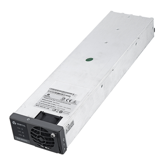
Inches: 1.7 (Height) X 3.3 (Width) X 13.0 (Depth) • Weight: 3 kg (6.6 lbs) • Indicators: a) Power (Green LED) b) Protection (Yellow LED) c) Alarm (Red LED) Vertiv | NetSure Rectifier Module User Manual (UM1R483000e3) | Rev. 1.0... -
Page 15: Operation
If batteries are used on the rectifier output, the batteries should support the load until the current limit set points can be re-established due to loss of a rectifier. Figure 5: Local Indicator Locations Vertiv | NetSure Rectifier Module User Manual (UM1R483000e3) | Rev. 1.0... -
Page 16: Installing Rectifiers
3. Loosen the captive screw on the module’s handle. Pull the handle down out from the module’s front panel (this will also retract the latch mechanism). See Figure 6. 4. Push the module completely into the shelf. Vertiv | NetSure Rectifier Module User Manual (UM1R483000e3) | Rev. 1.0... - Page 17 8. Certain functions (i.e. rectifier current limit, rectifier addressing) may require adjustment when adding or replacing a rectifier module. Refer to “Rectifier Current Limit” on page 15 and the Power System documentation for instructions. Figure 6: Installing Rectifier Module Vertiv | NetSure Rectifier Module User Manual (UM1R483000e3) | Rev. 1.0...
-
Page 18: Troubleshooting And Repair
1. Remove any object that may be blocking 1. Fan rotor blocked. the fan. 2. Ventilation blocked 2. Remove any object that may be blocking (inlet or outlet). the inlet or outlet. Vertiv | NetSure Rectifier Module User Manual (UM1R483000e3) | Rev. 1.0... -
Page 19: Replacement Procedures
3. Grasp the handle and pull firmly to remove the module from the shelf. 4. Place the replacement rectifier module into the mounting position without sliding it in completely. Vertiv | NetSure Rectifier Module User Manual (UM1R483000e3) | Rev. 1.0... -
Page 20: Rectifier Fan Replacement
8. Replace the Rectifier into the shelf. Refer to the previous procedure for step-by-step instructions. 9. Enable the external alarms, or notify appropriate personnel that this procedure is finished. 10. Ensure that there are no local or remote alarms active on the system. Vertiv | NetSure Rectifier Module User Manual (UM1R483000e3) | Rev. 1.0... - Page 21 Figure 7: Fan Replacement Vertiv | NetSure Rectifier Module User Manual (UM1R483000e3) | Rev. 1.0...
- Page 22 VertivCo.com | Vertiv Headquarters, 1050 Dearborn Drive, Columbus, OH, 43085, USA UM1R483000e3 (RH 07/23)
Need help?
Do you have a question about the NetSure R48-3000e3 and is the answer not in the manual?
Questions and answers