Table of Contents
Advertisement
Quick Links
SOYAL
ACCESS CONTROL SYSTEM
Contents
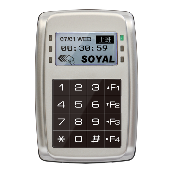
AR-327(H-V5):Touch-panel Metal Case
1
Products
2
AR-727(H-V5)
1
Products
2
User Guide
Installation
AR-327(H-V5)
3
4
1
2
5
AR-727(H-V5)
4
1
2
3
5
Connector Table
Cable:
CN4
P1
Wire Application
Wire
Lock Relay
1
Blue White (N.O.)DC24V1Amp
2
Purple White (N.C.)DC24V1Amp
Lock Relay COM
3
Door Contact
4
Orange
Exit Switch
5
Alarm Relay
6
Power
7
Thick Red
8
Thick Black DC 0V
Cable:
P2
CN5
Wire Application
Wire
Beeper
1
2
LED
3
Door Output
4
Blue White
5
Thin Green Wiegand DAT: 0 Input
Wiegand
6
Thin Blue
WG Door Contact
7
WG Exit Switch
8
Cable:
P3
CN7
Wire Application Wire
(AR-327H-V5 By
order)
TCP/IP Module
Output
®
AR-327 / AR-727HV5
3
P1
P4
3
Terminal Cables
P1
P4
Pull the cables from the square hole of the mounting plate.
Use a screw to the mounting plate onto the wall.
Attach the water proof strip to the body, then connect the terminal cables to the body
and attach the body to the mounting plate.
Use the Allen key and screws (accessories supplied) to assemble the body onto the
mounting plate.
Turn on the power, the LED will light and hear the beep sound, you will see "Ready""
on LCD board.
Attach the water proof strip to the mounting plate.
Pull the cables from the square hole of the mounting plate.
Use a screwdriver to screw the base onto the wall.
Connect the terminal cables to the body and attach the body to the mounting plate.
Assemble the covers with the Allen key and screws (accessories supplied).
Turn on the power, the LED will light and hear the beep sound, you will see "Ready""
on LCD board.
Color
Description
White
(COM)DC24V1Amp
Negative Trigger Input
Purple
Negative Trigger Input
Gray
N.O./N.C. Optional (by jumper)
DC 12V
Color
Description
Pink
Beeper Output 5V/100mA, Low
Yellow
Red LED Output 5V/20mA, Max
Brown
Green LED Output 5V/20mA, Max
Transistor Output Max. 12V/100mA
(Open Collector Active Low)
Wiegand DAT: 1 Input
Orange
Negative Trigger Input
Purple
Negative Trigger Input
Color
Description
1
---
---
2
---
---
3
Orange White Net - TX+
4
Orange
Net - TX-
5
Green White Net - RX+
6
Green
Net - RX-
7
---
---
4
P2
Water proof Strip
P5
P6
P2
P3
P5
P6
Main PCB
7
6
5
4
3
CN10
2
1
327(H-V5)
P8
Cable:
P4
Wire Application
RS-485 for Lift
Controller
Cable:
P5
Wire Application
Anti-Tamper
Switch
Cable:
P6
Wire Application
Power
Security trigger signal
Arming
Duress
5
Optional
AR-721RB
AR-821RB
Digital Relay
4
Tools
5
Optional
Water proof Strip
AR-821RB
Notice
1.Tubing: The communication wires and
power line should NOT be bound in the
same conduit or tubing.
2.Wire selection:Use AWG 22-24
Shielded Twist Pair to avoid star wiring
,CAT 5 cable for TCP/IP connection.
Don't equip reader and lock with the
same power supply. The power for
reader may be unstable when the lock
is activating, that may make the reader
malfunction.
3.Power supply:The standard
installation: Door relay and lock use the
same power supply, and reader use
independent power supply.
CN18
P4
CN6
7
P2
CN5
6
2
8
1
5
P3
7
4
CN7
Optional
Optional
6
8
3
P9
P7
5
2
7
CN9
4
CN11
1
6
6
6
3
5
4
5
5
2
4
P6
4
3
4
1
3
CN8
2
3
3
2
1
2
2
1
1
1
P1
3 2 1
CN4
P5
CN3
CN6
Wire
Color
Description
1
Thick Green RS-485(B-)
2
Thick Blue
RS-485(A+)
CN3
Wire
Color
Description
1
Red
N.C.
2
Orange
COM
3
Yellow
N.O.
CN8
Wire
Color
Description
1
Red
DC 12V Output
2
Purple
Security trigger signal Output
3
Red White
Arming Output
4
Yellow White Duress Output
V160304
P3
TCP/IP Module
and Cable
AR-721RB
Digital Relay
727H-V5 LCD-PCB
7
6
5
Optional
4
CN18
3
727(H-V5)
2
P8
1
Advertisement
Table of Contents

Related Manuals for Soyal AR-327


Summary of Contents for Soyal AR-327
- Page 1 SOYAL ® AR-327 / AR-727HV5 V160304 ACCESS CONTROL SYSTEM Contents AR-327(H-V5):Touch-panel Metal Case Products User Guide Terminal Cables Tools Optional Water proof Strip TCP/IP Module AR-721RB AR-821RB Digital Relay and Cable AR-727(H-V5) Products User Guide Terminal Cables Tools Optional Water proof Strip...
- Page 2 Blue Wiegand DAT: 1 Input Orange 8Ω / 1.5W (Max. Green Wiegand DAT: 0 Input DC 5V White Front Panel & Indicator AR-327 (H-V5) AR-727 (H-V5) Data Data [e.g.] 02/24←→02 24(Network Connected) Week Week Work Status Work Shift Status OK(Green)
- Page 3 SOYAL ® AR-327 / AR-727HV5 V160304 ACCESS CONTROL SYSTEM Strengthen security with AR-721RB Connect to Reader POWER POWER Door Contact 12VDC 12VDC Exit Switch Electric Bolt Electric Bolt N.C. N.C. RLED N.O. GLED Door Output WG 0 1 2 3...
- Page 4 0. UART Port IP Setting Open your Web Browser and input factory default IP address: http://192.168.1.127 If the IP address of AR-327(H-V5) / 727 (H-V5) has changed We must enter the new IP address. Log-in User Password When you choose the "Networking Setting" or "User Password" at first.
- Page 5 1141 Budapest, Fogarasi út 77. 1095 Budapest, Mester utca 34. Tel.: *220-7940, 220-7814, 220-7959, Tel.: *218-5542, 215-9771, 215-7550, 220-8881, 364-3428 Fax: 220-7940 216-7017, 216-7018 Fax: 218-5542 Mobil: 30 531-5454, 30 959-0930 Mobil: 30 940-1970, 30 959-0930 www.soyal.hu E-mail: info@delton.hu Web: www.delton.hu...
Need help?
Do you have a question about the AR-327 and is the answer not in the manual?
Questions and answers