Table of Contents
Advertisement
Quick Links
SOYAL
ACCESS CONTROL SYSTEM
Contents
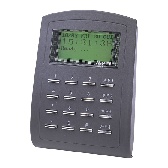
AR-327(H):Touch-panel Metal Case
1
Products
A.
B.
AR-727 (H)
1
Products
A.
B.
Installation
AR-327 (H)
3
4
2
5
AR-727 (H)
4
2
3
5
Notice
1.Tubing:
The communication wires and power line should NOT be bound in the same conduit or tubing.
2.Wire selection:
Use AWG 22-24 Shielded Twist Pair it sould avoid star wiring.
3.Power supply:
Don't equip reader and lock with the same power supply. The power for reader may be unstable when the lock is activating, that may make the
reader malfunction.
The standard installation: Lock relay and lock use the same power supply, and reader use independent power supply.
4.F4: At first time use, if appears no screen and green LED flashes, please press [F4] for 2 seconds.
Connector Table
AR-327 (H)
P3
P4
P2
P1
AR-727 (H)
P2
P1
P3
P4
®
AR-327 (H) / AR-727 (H)
2
User Guide
3
2
User Guide
3
Pull the cables from the square hole of the mounting plate.
Use a screw to the mounting plate onto the wall.
Attach the water proof strip to the body, then connect the terminal cables
to the body and attach the body to the mounting plate.
1
Use the Allen key and screws (accessories supplied) to assemble the
body onto the mounting plate.
Turn on the power, the LED will light and hear the beep sound, you will
see "Ready"" on LCD board.
Attach the water proof strip to the mounting plate.
Pull the cables from the square hole of the mounting plate.
1
Use a screwdriver to screw the base onto the wall.
Connect the terminal cables to the body and attach the body to the
mounting plate.
Assemble the covers with the Allen key and screws (accessories supplied).
Turn on the power, the LED will light and hear the beep sound, you will see
"Ready"" on LCD board.
Cable:
P1
Wire Application
Pin
Color
1
Blue White
Door Relay
2
Purple White
3
White
Common-COM-Point
Door contact
4
Orange
Exit Switch
5
Purple
6
Alarm Relay
Gray
Power
7
Thick Red
8
Thick Black
Cable:
P3
Wire Application
Pin
Color
1
Red
Tamper Switch
2
Orange
3
Yellow
Terminal Cables
P1
P2
P3
P4
Terminal Cables
P1
P2
P3
P4
Cable:
Description
Wire Application
Networking
(N.O.)DC24V1Amp
(N.C.)DC24V1Amp
(COM)DC24V1Amp
Wiegand
Negative Trigger Input
Negative Trigger Input
N.O./N.C. Options
(by jumper)
Buzzer
DC 12V
LED
DC 0V
Cable:
Description
Wire Application
N.C.
Arming Setting Input
COM
Serial Port
N.O.
Arming Status
indication (light)
Card existing indication
4
4
Tools
AR-327(H) 13.56MHz Notice
Sensing range of metal controller is small, the
proposed sensing card should step aside, do
not fully cover number keys.
P2
Pin
Color
Description
1
Thick Green
RS-485 (B-)
2
Thick Blue
RS-485 (A+)
3
Blue
WG DAT: 1 Inpu
ABA Data Input
4
Green
WG DAT: 0 Input
ABA Clock Input
5
Pink
Buzzer Output 5V/100mA, MAX
6
Brown
LED Green Output 5V/20mA, MAX
7
Yellow
LED Red Output 5V/20mA, MAX
P4
Pin
Color
Description
1
Orange White
2
Yellow White
Serial output (Transistor open
collector) (4800, N,8,1)
3
Red White
Arming output (Active low)/
Security trigger signal Output
4
Brown White
Output LOW when card present
V140423
5
Water proof Strip
5
Water proof Strip
Latch type
Advertisement
Table of Contents

Related Manuals for Soyal AR-727H


Summary of Contents for Soyal AR-727H
- Page 1 SOYAL ® AR-327 (H) / AR-727 (H) V140423 ACCESS CONTROL SYSTEM Contents AR-327(H):Touch-panel Metal Case Products User Guide Terminal Cables Tools Water proof Strip AR-727 (H) Water proof Strip Products User Guide Terminal Cables Tools Installation AR-327(H) 13.56MHz Notice AR-327 (H) Pull the cables from the square hole of the mounting plate.
- Page 2 LCD Access Controller Metal Case / Standard V140423 Wiring Diagram Connect to Electric Bolt or Magnet Lock Connect to Electric Strike POWER Magnetic Lock POWER 12VDC 12VDC Electric Bolt Electric Strike N.O. N.C. N.O. N.O. Controller Controller EXIT EXIT POWER POWER Request To Exit Request To Exit...
- Page 3 Door-H input (door NO. of controller); Door-L input (door No. of the reader). F: Break RTN 17: Alarm [e.g.] AR-727H is a controller and its Node ID is 8. G: Out 31: Anti-pass back Error H: Return Door-H input ; Door-L input D.
- Page 4 LCD Access Controller Metal Case / Standard V140423 E.Control Mode (M4/M6/M8) Enter program mode → Tools → Control Mode → 1:M4, 2:M6, 3:M8 (refer to following table) → Succeeded User Networking/ Auto-show Event log Anti Time Lift Anti-pass Mode Access Mode Capacity Standalone Duty time...
- Page 5 CÔNG TY CỔ PHẦN THÀNH AN Địa chỉ: Tầng 5 - Số 184 Nguyễn Tuân - Thanh Xuân- Hà nội Email: info@vken.vn Tel: 0904 954 981 MST: 0101219662 Website: www.Vken.vn CATALOGUES Kính chào Quý Khách Hàng ! VKEN chúng tôi trân trọng gửi tới Quý Khách Hàng một số thông tin về sản phẩm do VKEN cung cấp, chúng tôi cam kết hàng bán ra thị...
Need help?
Do you have a question about the AR-727H and is the answer not in the manual?
Questions and answers