Table of Contents
Advertisement
Quick Links
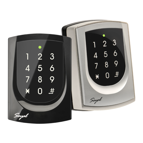
SOYAL
ACCESS CONTROL SYSTEM
Contents
AR-725-E-M
1
Products
A.
B.
AR-725-E
1
Products
A1.
E.
AR-725 (X)
1
Products
A2.
A3.
Parts Description
Button Head Pozidriv
a.
Tapping Screw: M3x10
d.
Security Torx Screw:
M3.5x15
Installation
AR-725-E-M
3
A.
A.
2
C.
4
1
B.
c.
AR-725-E
F.
1
AR-725 (X)
A1.
A3.
1
b.
G.
®
C.
D.
F.
B.
C.
G.
b.
e.
A.
B.
C.
B.
6
5
F.
E.
A1.
3
4
e.
f.
5
A1.+A3.
H.
A2.
e.
f.
AR-725-E
2
Terminal Cables
CN4
CN6
CN3
CN11
Optional wafer cables for additional purchase for TTL
※
integration with peripheral devices or floor control.
2
Terminal Cables
CN4
CN6
CN3
CN11
Optional wafer cables for additional purchase for TTL
※
integration with peripheral devices or floor control.
H.
D.
Button Head Pozidriv
Slotting Screw: 2.5x10
Flat Head Hex Socket
Screw: M3x8
Pull the cables from the square access hole of the mounting plate C.
Use a screwdriver to screw the metal plate C to the wall.
A.
7
Take off the plastic mounting plate B from the body A, and pull the cables
C.
through the access hole of C and B, then connect to the body A.
Assemble plate B with the body A, and embed the water proof strip D
onto the plastic side frame.
d.
8
Assemble the body A onto the mounting plate C with the Allen key and
D.
g.
screws (accessories supplied).
Turn on the power and LED will light and beep will sound.
Use a screwdriver to screw the base F onto the wall.
Attach the water proof gasket to the body A1, and pull the cables
2
from the square hole of the base F, and connect to the body A1.
Assemble the body A1 with the base F.
Screw A1 and F tight with the Allen key and screws (accessories
supplied).
Turn on the power and LED will light and beep will sound.
Put on G, and attach A1 onto the plastic plate A3, and screw it with
the Allen key and screws (accessories supplied).
D.
Put the ring O on the metal frame, and put them together onto the
reader A1+A3, and screw them and buckle up the 4 buckles on the
4
back.
a.
Embed the water proof strip D onto the frame side of the base.
5
Following by the install process of AR-725-E-M.
- 1 -
CN7
CN5
CN8
CN11
※
CN5
CN7
CN8
CN11
※
2
Tools
a x2
b x2
c x2
Flat Head Cap Philips
c.
Tapping Screw: 4x19.1
f.
V220916
3
Tools
c x2
d x1
f x1
3
Tools
e x1
d x1
f x1
Advertisement
Table of Contents

Subscribe to Our Youtube Channel
Related Manuals for Soyal AR-725-E


Summary of Contents for Soyal AR-725-E
- Page 1 Put the ring O on the metal frame, and put them together onto the reader A1+A3, and screw them and buckle up the 4 buckles on the back. Embed the water proof strip D onto the frame side of the base. Following by the install process of AR-725-E-M. - 1 -...
-
Page 2: Connector Table
SOYAL ® AR-725-E V220916 ACCESS CONTROL SYSTEM AR-725-E AR-725-E(Metal Housing) 78.5 21.5 25.7 14.7 59.7 25.5 29.9 Front View Side view Front View Side view Notice 1. Tubing: The communication wires and power line should NOT be bound in the same conduit or tubing. -
Page 3: Wiring Diagram
Access controller Illuminated Touch-panel V220916 Wiring Diagram Connect to Electric Bolt AR-321H Connect to Magnet Lock Electric Bolt N.O. POWER AR-1207 12VDC N.C. POWER P.T.Exit Magnet Lock 12VDC Main Port N.O. Main Port WG Port N.C. WG Port N.O. N.O. Controller Controller EXIT... -
Page 4: Controller Mode
,AR-725-E become WG mode (28 WG Mode Controller Mode 701ServerSQL Parameter Setting 701ServerSQL Parameter Setting 1. AR-725-E can be set up as WG26/WG34/ WG64 while the Controller is in WG Mode. These Controller can also be paired with the AR-725-E AR-725-E Controller that has WG input function. - Page 5 Access programming mode → 20 0 or 1 0 or 1= Enable target unit (0=Main Controller Parameter Setting,1=WG Input Port Parameter Setting) [e.g.] If the AR-725-E set to exit reader, WG Reader set to access reader. Access programming mode → 20 → 20...
-
Page 6: Arming Mode
(NN=00~15); HHMMhhmm=Starting time to ending time; 7123456H= 7 days of week + Holiday (F= 0: disable; 1: enable)] [e.g.]AR-725-E (without WG reader), to set second time zone which could be passed only at 9:30am to 4:20pm on Mon, Wed and Fri. -
Page 7: Restoring Factory Settings
Firmware Upgrade Get the upgrade software from SOYAL or our distributor and run “UdpUpdater” software Execute the software The software is Login the SOYAL web to downloads Update the firmware [Please login the SOYAL web to download the new ISP Firmware.]... -
Page 8: Current State
Illuminated Touch-panel V220916 IP Setting IP Setting Open your Web Browser and input factory default IP address: http://192.168.1.127 If the IP address of AR-725-E has changed We must enter the new IP address. Page menu Page menu Monitor the on-line computer... -
Page 9: Command List
Exiting programming mode Exiting programming mode and enabling all device Including AR-725-E, WG Reader into arming status. Enabling each device into arming status. U=Enable target unit (0=AR-725-E , 1=WG Reader) NNN=Node ID,(001~254) Node ID setting MMM=AR-725-E Door Number,(001~255) AAA=WG Reader Door Number,(001~255) default value = 192.168.1.127... - Page 10 MM= Month of year (01=Jan...10=Oct.) Holiday Setting MMDD DD= Date of month (01=1st day of month) F= 0:Delete ; 1: Add M=AR-725-E; W=WG Reader (0=disable; 1=enable) Enabling or Disabling into Full Access status A=0:AR401RO B=0: 9600(default value) RS485 port function setting...
- Page 11 SOYAL ® AR-725-E V220916 ACCESS CONTROL SYSTEM (Main Controller Parameter Setting) (WG Input Port Parameter Setting) ※Default Value Function Option Value Application Enable Egress Beep Sounds 0: Disable ※1: Enable 0 Networking/Stand-Alone ---- ---- ---- 1 ---- ---- ---- ----...
Need help?
Do you have a question about the AR-725-E and is the answer not in the manual?
Questions and answers