Table of Contents
Advertisement
Quick Links
SOYAL
ACCESS CONTROL SYSTEM
Contents
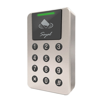
AR-363-E
1
Products
Installation
F.
1
Use a screwdriver to screw the base F onto the wall.
Attach the water proof gasket to the base F, and pull the cables from
the square hole of the base F, and connect to the body A1.
Assemble the body A1 with the base F.
Screw A1 and F tight with the Allen key and screws (accessories
supplied).
Turn on the power and LED will light and beep will sound.
Notice
1. Tubing: The communication wires and power line should NOT be bound in the same conduit or tubing.
2. Cable selection: Use AWG 22-24 Shielded Twist Pair to avoid star wiring. Use CAT5 for TCP/IP connection.
3. Power supply: Don't equip reader and lock with the same power supply. The power for reader may be unstable when the lock is activating, that may make the
reader malfunction. The standard installation: Door relay and lock use the same power supply, and reader use independent power supply.
Connector Table
CN9
CN11
CN3
®
2
Terminal Cables
CN4
CN6
CN3
CN11
Optional wafer cables for additional purchase for TTL
※
integration with peripheral devices or floor control.
F.
E.
A1.
3
4
e.
f.
5
CN8
CN4
CN5
CN6
CN7
AR-363-E
3
Tools
CN5
CN7
CN8
CN11
※
Dimension(mm)
2
10
Front View
Cable:
CN3
Wire Application Wire
1
Anti-Tamper
2
Switch
3
Cable:
CN4
Wire Application Wire
1
Lock Relay
2
3
Common-COM-Point
Door Sensor
4
Exit Switch
5
Alarm Relay
6
7
Power
8
- 1 -
3
x1
Flat Head Hex Socket
Ethernet Module Only
Screw: M3x8
68.3
6.1
25
Side view
Color
Description
Red
N.C.
Orange
COM
Yellow
N.O.
Color
Description
Blue White (N.O.)DC24V1Amp
Purple White (N.C.)DC24V1Amp
White
(COM)DC24V1Amp
Orange
Negative Trigger Input
Purple
Negative Trigger Input
Transistor Output Max. 12V/100mA
Gray
(Open Collector Active Low)
Thick Red DC 12V
Thick Black DC 0V
V230322
Optional
30
Advertisement
Table of Contents

Related Manuals for Soyal AR-363-E


Summary of Contents for Soyal AR-363-E
- Page 1 SOYAL ® AR-363-E V230322 ACCESS CONTROL SYSTEM Contents AR-363-E Tools Optional Products Terminal Cables Flat Head Hex Socket Ethernet Module Only CN11 ※ Screw: M3x8 CN11 Optional wafer cables for additional purchase for TTL ※ integration with peripheral devices or floor control.
-
Page 2: Wiring Diagram
SOYAL ® AR-363-E V230322 ACCESS CONTROL SYSTEM AR-725-E Cable: Cable: Wire Application Wire Color Description Wire Application Wire Color Description Beeper Pink Beeper Output 5V/100mA, Low Power DC 12V Output Yellow Red LED Output 5V/20mA, Max Security trigger signal Purple... -
Page 3: Access Controller
WG Mode / Controller Mode Setting Method ,AR-725-E become WG mode (28 WG Mode Controller Mode 1. AR-363-E can be set up as WG26/WG34/ 701ServerSQL Parameter Setting 701ServerSQL Parameter Setting WG64 while the Controller is in WG Mode. These Controller can also be paired with the Controller that has WG input function. - Page 4 SOYAL ® AR-363-E V230322 ACCESS CONTROL SYSTEM Adding and Deleting Tag Add New Tags Add by Presenting Tags (apply to Single Tag or a Batch of Tags) ※Important Notice: Please remember the last user address being added to make sure the old user data is not being over written with the new card in the future.
-
Page 5: Anti-Pass-Back
Access programming mode → 20 0 or 1 0 or 1= Enable target unit (0=Main Controller Parameter Setting,1=WG Input Port Parameter Setting) [e.g.] If the AR-363-E set to exit reader, WG Reader set to access reader. Access programming mode → 20 → 20... -
Page 6: Arming Mode
Access controller Illuminated Touch-panel V230322 Set up auto-open time zone Access programming mode → 08 HHMMhhmm 7123456H [M=AR-725-E; W=Reader(0=disable,1=enable); NN: 16 sets of auto-open zone (NN=00~15); HHMMhhmm=Starting time to ending time; 7123456H= 7 days of week + Holiday (F= 0: disable; 1: enable)] [e.g.]AR-725-E (without WG reader), to set second time zone which could be passed only at 9:30am to 4:20pm on Mon, Wed and Fri. -
Page 7: Restoring Factory Settings
Firmware Upgrade Get the upgrade software from SOYAL or our distributor and run “UdpUpdater” software Execute the software The software is Login the SOYAL web to downloads Update the firmware [Please login the SOYAL web to download the new ISP Firmware.]... - Page 8 Illuminated Touch-panel V230322 IP Setting IP Setting Open your Web Browser and input factory default IP address: http://192.168.1.127 If the IP address of AR-363-E has changed We must enter the new IP address. Page menu Page menu Monitor the on-line computer...
-
Page 9: Command List
IP Address assign (Must power reset) will disable DHCP 255255255000 Netmask 192168001254 Gateway assign U=Enable target unit (0=AR-363-E , 1=WG Reader) Door relay time setting TTT=Door relay time;000 (Output constantly) 001~600=1-600 Sec.;601~609=0.1~0.9Sec. TTT=Alarm relay time;000 (Output constantly) Alarm relay time setting 001~600=1~600 Sec. - Page 10 MM= Month of year (01=Jan...10=Oct.) Holiday Setting MMDD DD= Date of month (01=1st day of month) F= 0:Delete ; 1: Add M=AR-363-E; W=WG Reader (0=disable; 1=enable) Enabling or Disabling into Full Access status A=0:AR401RO B=0: 9600(default value) RS485 port function setting...
- Page 11 SOYAL ® AR-363-E V230322 ACCESS CONTROL SYSTEM (Main Controller Parameter Setting) (WG Input Port Parameter Setting) ※Default Value Function Option Value Application Enable Egress Beep Sounds 0: Disable ※1: Enable 0 Networking/Stand-Alone ---- ---- ---- 1 ---- ---- ---- ----...
Need help?
Do you have a question about the AR-363-E and is the answer not in the manual?
Questions and answers