Advertisement
Quick Links
SOYAL
ACCESS CONTROL SYSTEM
Contents
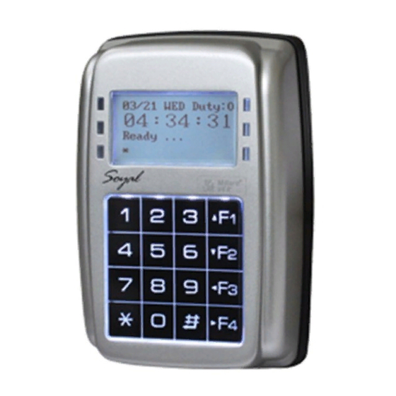
AR-327H [Metal Case]
1
Products
A.
B.
AR-727H
1
Products
A.
B.
Installation
AR-327H
3
4
2
5
AR-727H
4
2
3
5
Notice
1.Tubing:
The communication wires and power line should NOT be bound in the same conduit or tubing.
2.Wire selection:
Use AWG 22-24 Shielded Twist Pair it sould avoid star wiring.
3.Power supply:
Don't equip reader and lock with the same power supply. The power for reader may be unstable when the lock is activating, that may make the
reader malfunction.
The standard installation: Door relay and lock use the same power supply, and reader use independent power supply.
Connector Table
AR-327H
P3
P4
P2
P1
AR-727H
P2
P1
P3
P4
®
2
User Guide
3
2
User Guide
3
Pull the cables from the square hole of the mounting plate.
Use a screwdriver to screw the mounting plate onto the wall.
Attach the water proof strip to the body, then connect the terminal cables to the body and attach the body to the
1
mounting plate.
Use the Allen key and screws (accessories supplied) to assemble the body onto the mounting plate.
Turn on the power, the LED will light and hear the beep sound, you will see "Ready"" on LCD board.
Attach the water proof strip to the mounting plate.
1
Pull the cables from the square hole of the mounting plate.
Use a screwdriver to screw the base onto the wall.
Connect the terminal cables to the body and attach the body to the mounting plate.
Assemble the covers with the Allen key and screws (accessories supplied).
Turn on the power, the LED will light and hear the beep sound, you will see "Ready"" on LCD board.
Cable:
P1
Wire Application
Pin
Color
Door Relay
1
Blue White
2
Purple White
3
White
Common-COM-Point
Door Sensor
4
Orange
Exit Switch
5
Purple
Alarm Relay
6
Gray
Power
7
Thick Red
8
Thick Black
Cable:
P3
Wire Application
Pin
Color
Tamper Switch
1
Red
2
Orange
3
Yellow
AR-327H / AR-727H
Terminal Cables
P1
P2
P3
P4
Terminal Cables
P1
P2
P3
P4
Cable:
Description
Wire Application
(N.O.)DC24V1Amp
Networking
(N.C.)DC24V1Amp
(COM)DC24V1Amp
Wiegand
Negative Trigger Input
Negative Trigger Input
N.O./N.C. Options
(by jumper)
Buzzer
DC 12V
LED
DC 0V
Cable:
Description
Wire Application
N.C.
Arming Setting Input
COM
Serial Port
N.O.
Arming Status
indication (light)
Card existing indication
4
Tools
4
Tools
P2
Pin
Color
Description
1
Thick Green
RS-485 (B-)
2
Thick Blue
RS-485 (A+)
3
Blue
WG DAT: 1 Inpu
ABA Clock Input
4
Green
WG DAT: 0 Input
ABA Data Input
5
Pink
Buzzer Output 5V/100mA, MAX
6
Brown
LED Green Output 5V/20mA, MAX
7
Yellow
LED Red Output 5V/20mA, MAX
P4
Pin
Color
Description
1
Orange White
2
Yellow White
Serial output (Transistor open
collector) (4800, N,8,1)
Arming output (Active low)
3
Red White
Output LOW when card present
4
Brown White
V091021
5
Water proof Strip
5
Water proof Strip
Latch type
Advertisement

Related Manuals for Soyal AR-327H


Summary of Contents for Soyal AR-327H
- Page 1 SOYAL ® AR-327H / AR-727H V091021 ACCESS CONTROL SYSTEM Contents AR-327H [Metal Case] Products User Guide Terminal Cables Tools Water proof Strip AR-727H Water proof Strip Products User Guide Terminal Cables Tools Installation AR-327H Pull the cables from the square hole of the mounting plate.
- Page 2 RLED Node ID 254 AR-716E Host POWER 12VDC Controller Controller Door No. 9 Door No. 16 Front Panel & Indicator AR-327H AR-727H Data Data Week Week Work Status Work Shift Status Arming (Green) Arming Setting Input Indicator (Red) Arming(Green) 18/02...
- Page 3 1~254(door No. of its controllen) → Input Door number L: 1~254(door No. of reader) → Succeeded D: Overtime Off 11: Normal Access [e.g.] AR-327H is the 8th slave reader under the 16th AR-716E. E: Break Out 16: Egress (Request to exit) Door-H input (door NO.
- Page 4 LCD Access Controller Metal Case / Standard V091021 D.Setting up the control mode (M4/M6/M8) Access programming mode → Tools → Control Mode → 1:M4, 2:M6, 3:M8(refer to below chart) → Succeeded User Networking/ Auto-show Event log Anti Time Lift Anti-pass- Mode Access Mode Capacity...
Need help?
Do you have a question about the AR-327H and is the answer not in the manual?
Questions and answers