Table of Contents
Advertisement
Quick Links
SOYAL
ACCESS CONTROL SYSTEM
Contents
1
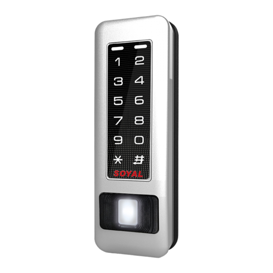
Product
AR-331-E
AR-331-EF
Installation
Peel
off frame
rubber
4
Peel
off
screw
rubber
Peel off screw hole rubbers and frame rubber from rubber pad
Put screw rubbers on the back side of the mounting plate and pull the
cables from the square hole of the mounting plate.
Put a frame rubber on the frame groove of body
Connect the terminal cables to the body and attach the body to the
mounting plate.
Assemble the covers with the Allen key and screws (accessories supplied).
Turn on the power and LED will light and beep will sound.
Connector Table
CN4
CN2
CN9
CN3
CN5
Cable:
CN1
Wire Application Wire
Color
1
Blue White (N.O.)DC24V1Amp
Lock Relay
2
Purple White (N.C.)DC24V1Amp
3
White
Common-COM-Point
Door Contact
4
Orange
Exit Switch
5
Purple
Alarm Relay
6
Gray
7
Thick Red DC 12V
Power
8
Thick Black DC 0V
Cable:
CN2
Wire Application Wire
Color
1
White
DI1
2
Beeper
Pink
3
Yellow
LED
4
Brown
Door Output
5
Blue White
6
Thin Green Wiegand DAT: 0 Input
Wiegand
7
Thin Blue Wiegand DAT: 1 Input
WG Door Contact
8
Orange
WG Exit Switch
9
Purple
2
Terminal Cables
CN1
CN2
CN4
CN5
CN6
7
Frame
6
Rubber
5
5
Put on/Take off together
CN1
8
8
9
CN6
CN11
Description
(COM)DC24V1Amp
Negative Trigger Input
Negative Trigger Input
Transistor Output Max. 12V/100mA
(Open Collector Active Low)
Description
Reserved
Beeper Output 5V/100mA, Low
Red LED Output 5V/20mA, Max
Green LED Output 5V/20mA, Max
Transistor Output Max. 12V/100mA
(Open Collector Active Low)
Negative Trigger Input
Negative Trigger Input
AR-331-E/EF
3
Tools
Flat Head Cap Philips
Tapping Screw: 4x20
Security Torx: M3x10
Security Torx Wrenches
Left LED
1
Blue
3
4
2
Screws
Yellow
Rubber
While power on the device,
hands off the touch panel
for 10 sec. to make sure
a successful activation.
Cable:
CN3
Wire Application Wire
TCP/IP Output
Cable:
CN4
Wire Application Wire
RS-485 for Lift
Controller
Cable:
CN5
Wire Application Wire
Anti-Tamper
Switch
Cable:
CN6
Wire Application Wire
Power
Security trigger signal
Arming
Duress
Cable:
CN9
Wire Application Wire
TTL Output
4
Accessories
5
Option
Rubber Pad
Front Panel & Indicator
Right LED
Descrption
Green
Arming / Blue LED
Input (Active High)
Yellow LED Input
Red
(Active High)
1
2
3
4
5
6
7
8
9
0
最佳感應區
Color
Description
1
---
---
2
---
---
3
Orange White Net - TX+
4
Orange
Net - TX-
5
Green White Net - RX+
6
Gerrn
Net - RX-
7
---
---
Color
Description
1
Thick Green RS-485(B-)
2
Thick Blue RS-485(A+)
Color
Description
1
Red
N.C.
2
Orange
COM
3
Yellow
N.O.
Color
Description
1
Red
DC 12V Output
2
Purple
Security trigger signal Output
3
Red White Arming Output
4
Yellow White Duress Output
Color
Description
1
Blue
CLK
2
Red
DC 5V
3
Orange
RX
4
White
TE
5
Yellow
TX
6
Black
DC 0V
V200422
TCP/IP
RJ45
Module
Descrption
Power-on/Stand-by
/OK
Error/Alarm
Advertisement
Table of Contents

Related Manuals for Soyal AR-331-E


Summary of Contents for Soyal AR-331-E
- Page 1 SOYAL AR-331-E/EF V200422 ACCESS CONTROL SYSTEM Contents Product Terminal Cables Tools Accessories Option Flat Head Cap Philips Tapping Screw: 4x20 Security Torx: M3x10 TCP/IP Security Torx Wrenches Rubber Pad RJ45 Module AR-331-E AR-331-EF Installation Front Panel & Indicator Frame Left LED...
- Page 2 WG 1 POWER POWER 12VDC 12VDC AR-331-E/EF become WG mode 331-E/EF WGoutput 331-E/EF Master 1. When AR-331-E/EF become WG mode,it can be used with any controllers. Duress RLED 2. AR-331-E/EFsupport Anti-pass-back by finger or card. GLED Door Output WG 0 ※Using Rule :...
- Page 3 (NN=00~15); HHMMhhmm=Starting time to ending time; 7123456H= 7 days of week + Holiday (F= 0: disable; 1: enable)] [e.g.] AR-331-E/EF(without WG reader), to set second time zone which could be passed only at 9:30am to 4:20pm on Mon, Wed and Fri.
- Page 4 2. For dual-fingerprint sensor module version, user just can select one of fingerprint sensor for identification and can't put two fingerprints to different sensor at the same time. 3. Extra WG keypad panel is needed for adding card or downloading data connected to PC. 4. Each finger need to be collected 1 times enrolling for AR-331-E/EF. J. The process of FP identification 1.
- Page 5 Access programming mode → 39 99999 (Reference to picture) Firmware Upgrade Get the upgrade software from SOYAL or our distributor and run “UdpUpdater” software Execute the software The software is within SOYAL CD or Login the SOYAL web to downloads Update the firmware [Please login the SOYAL web to download the new ISP Firmware.]...
- Page 6 Biometrics Device Access controller Fingerprint V200422 IP Setting Open your Web Browser and input factory default IP address: http://192.168.1.127 If the IP address of AR-331-E/EF has changed We must enter the new IP address. Page menu Monitor the on-line computer IP Setting...
- Page 7 PPPP=4-digit PWD (0001-9999) Default value:1234 Enabling or Disabling into arming status Card+NNNN NNNN:Arming PWD Enabling or Disabling each device into arming status. Card+NNNN U=Enable target unit (0=AR-331-E/EF, 1=WG Reader) Enabling all device into arming status. Card+NNNN all device into arming status. Card+NNNN Disabling U=Enable target unit (0=AR-331-EF , 1=WG Reader)
- Page 8 Biometrics Device Access controller Fingerprint V200422 Command List (By WG Keyboard) Function Command Exposition M=AR-331-EF ; W=WG Reader (0=disable; 1=enable) Enabling or Disabling into Full Access status A=0:AR401RO B=0: 9600(default value) RS485 port function setting 1:Host (default value) 1: 19200 2:LED Panel 2: 38400 (Needs to be restarted after setting)
Need help?
Do you have a question about the AR-331-E and is the answer not in the manual?
Questions and answers