Table of Contents
Advertisement
Quick Links
Advertisement
Table of Contents

Subscribe to Our Youtube Channel
Related Manuals for Saluki ADS2202A


Summary of Contents for Saluki ADS2202A
- Page 1 ADS2202A (Ku-band) Radar Detection Device User Manual Saluki Technology Inc.
-
Page 2: Table Of Contents
Tel: 886.909 602 109 Email: sales@salukitec.com www.salukitec.com Content Chapter 1 Overview............................. 3 1.1 Background............................3 1.2 Main Functions............................ 3 1.3 Technical Specifications........................3 Chapter 2 Installation...........................6 2.1 Product Structure..........................6 2.2 Installation Method..........................7 2.3 Precautions............................9 Chapter 3 Introduction of PC Software.......................11 3.1 Precautions............................ -
Page 3: Chapter 1 Overview
In addition, the product has an input interface reserved for remote control and networking. Compared with the same type of products, ADS2202A has the advantages of good portability, long detection power and high detection accuracy. - Page 4 Tel: 886.909 602 109 Email: sales@salukitec.com www.salukitec.com Table 1.1 Technical specifications Parameters ADS2202A Frequency Band Frequency 16GHz Frequency Point Adjustable Transmit Signal Bandwidth ≤ 40MHz System One-dimensional active phased array Pitch electronic scanning, Scan Mode Azimuth mechanical scanning Turntable Horizontal Speed...
- Page 5 Tel: 886.909 602 109 Email: sales@salukitec.com www.salukitec.com Turntable Dimension 320mm*310mm*250mm Waterproof and Moistureproof IP56...
-
Page 6: Chapter 2 Installation
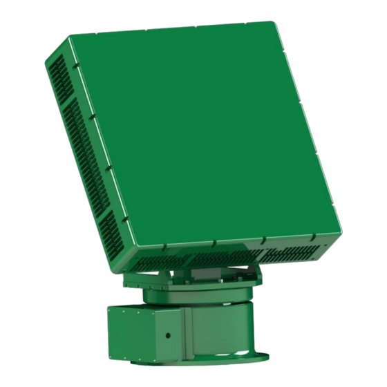
Figure 2.2 Radar host and turntable diagram ADS2202A radar is mainly composed of radar host, radar bracket, turntable and PC software. The radar machine diagram is shown in Figure 2.1. The radar host and turntable diagram is shown in Figure 2.2. The packing list is shown in the table below. -
Page 7: Installation Method
Tel: 886.909 602 109 Email: sales@salukitec.com www.salukitec.com Turntable 1 unit Mounting screws 1 set PC software 1 set User manual 1 pcs Test report 1 pcs Certificate 1 pcs Power aviation connector 1 pcs Network port aviation connector 1 pcs Power adapter 1 pcs Machine bracket... - Page 8 Tel: 886.909 602 109 Email: sales@salukitec.com www.salukitec.com Figure 2.3 Radar interface diagram Table 2.2 Radar interface Name Note Radar host Ethernet port Radar host power interface Turntable output Ethernet port Turntable output power interface Turntable input Ethernet port Turntable test port Please put on a waterproof cap.
-
Page 9: Precautions
Tel: 886.909 602 109 Email: sales@salukitec.com www.salukitec.com 2.2.2 Installation Instructions Figure 2.4 Screw mounting position diagram As shown in Figure 2.4, the 6 screws at "2" are used to fix the turret bracket on the turret; the 6 screws at "1" are used to fix the radar main unit to the turret bracket;... - Page 10 Tel: 886.909 602 109 Email: sales@salukitec.com www.salukitec.com Do not have metal coverings near the radar; When the radar works in the “receive and receive power-on” mode, there can be no people around; The use of the radar site must be guaranteed to be unobstructed; The radar will rotate when working, and the radar stand must be fixed reliably;...
-
Page 11: Chapter 3 Introduction Of Pc Software
Tel: 886.909 602 109 Email: sales@salukitec.com www.salukitec.com Chapter 3 Introduction of PC Software 3.1 Precautions When the radar is working ("transmission and power-on" mode), please ensure that there are no other people around the radar; The interface parameters are all values that meet the performance after factory debugging. Please contact the manufacturer before modifying the parameters. -
Page 12: Operating Steps
Tel: 886.909 602 109 Email: sales@salukitec.com www.salukitec.com Install “WinPcap_4_1_3.exe”; Run “anti_uav_radar.exe”; 3.4 Operating Steps Open “anti_uav_radar.exe”, and the “Network Port Selection” window will pop up, select the network port (usually Ethernet port) connected to the radar; If the radar is working properly, select “System Control / Antenna Power-on Mode” on the main interface as “Transceiver and Power-on”. -
Page 13: Introduction Of Interface Parameters
Tel: 886.909 602 109 Email: sales@salukitec.com www.salukitec.com 3.5 Introduction of Interface Parameters 3.5.1 Main interface(Control and track display interface) Main interface is shown in Figure 3.2. Figure 3.2 Main interface “1” is the system status, and the system information such as the current azimuth and elevation angle of the radar is ... - Page 14 Tel: 886.909 602 109 Email: sales@salukitec.com www.salukitec.com Figure 3.3 Track map 3.5.2 Other hardware settings Figure 3.4 Other settings interface When you click the “Other Radar Settings” button on the main interface, the “Other Radar Settings” interface will pop up. See Figure 3.4.
- Page 15 Tel: 886.909 602 109 Email: sales@salukitec.com www.salukitec.com Note: If you have modified some parameters, be sure to click "Apply" or "OK" to make it work. 3.5.3 Radar software settings Figure 3.5 Software settings Figure 3.6 Software settings interface As shown in Figure 3.5, after clicking “Settings - Software Settings” in the menu bar at the top left of the main interface, the “Radar Software Settings”...
-
Page 16: Main Functions
Tel: 886.909 602 109 Email: sales@salukitec.com www.salukitec.com 3.6 Main Functions 3.6.1 Conversion between radar coordinate system and northbound coordinate system Figure 3.7 Radar coordinate system Figure 3.8 Northbound coordinate system The radar coordinate system is a standard Cartesian coordinate system (Cartesian coordinate system), as shown in Figure 3.7 The target azimuth obtained by radar detection is the angle from the x-axis counterclockwise rotation to the radar target connection, so the azimuth increases counterclockwise, the positive x-axis represents 0 degrees, and the positive y-axis represents 90 degrees. - Page 17 Tel: 886.909 602 109 Email: sales@salukitec.com www.salukitec.com That is, the azimuth angle of the north coordinate system is equal to 450 degrees minus the azimuth angle of the radar coordinate system, and the modulo is taken for 360 degrees (note: floating point number modulo). 3.6.2 Azimuth pitch correction function The software can correct the azimuth and elevation angles analyzed in the message.
- Page 18 Tel: 886.909 602 109 Email: sales@salukitec.com www.salukitec.com minimum can be set to 2. If you want to upload a relatively small number of tracks, you can increase the “Min_TT”, but correspondingly, the time from the start of the track to the time the target device receives the track will increase. Figure 3.10 Select track or all output diagram Figure 3.11 Select the track and send...
- Page 19 Tel: 886.909 602 109 Email: sales@salukitec.com www.salukitec.com 3.6.4 Data collection function The software can collect raw data messages received by the host computer software, which is convenient for data playback and analysis. In the “Data Recording and Playback” area of the main interface, cancel the “Data Readback Check”...
- Page 20 Tel: 886.909 602 109 Email: sales@salukitec.com www.salukitec.com (a) Select source address (b) Select destination address (c) Apply filter Figure 3.14 Wireshark set filter criteria and apply filter criteria (a) Stop data collection...
- Page 21 Tel: 886.909 602 109 Email: sales@salukitec.com www.salukitec.com (b) Export file (c) Set the export file format Figure 3.15 Wireshark stop collection and export file...
- Page 22 Tel: 886.909 602 109 Email: sales@salukitec.com www.salukitec.com 3.6.5 Data readback function After the data acquisition is completed, the software can read back the saved radar message files. First, check "Data Recording and Playback / Data Readback Check"; then, click "Select Data File", select the message file in the pop-up window;...
- Page 23 Tel: 886.909 602 109 Email: sales@salukitec.com www.salukitec.com Figure 3.17 Silent setting (a) Lower bound 315°, upper bound 45° (b) Lower bound 45°, upper bound 315° Figure 3.18 Setting silent area 3.6.7 Data filter function The software can filter the input target original points, such as the target within the preset speed range or within the preset height range.
- Page 24 Tel: 886.909 602 109 Email: sales@salukitec.com www.salukitec.com bound is processed during data processing. Taking the distance as an example, if the distance selection is checked, the lower bound is set to 500 and the upper bound is set to 1000, only the original trace with the slant range in the range [500, 1000] is actually processed.
-
Page 25: Interface Protocol
Tel: 886.909 602 109 Email: sales@salukitec.com www.salukitec.com Figure 3.19 Open the latitude and longitude conversion distance bearing window Figure 3.20 Longitude and latitude conversion distance azimuth window 3.7 Interface Protocol The protocol for the track output is shown in Table 3.1. The latest points of each track are as follows: Table3.1 Track output interface protocol Based on UDP transmission, Adjustable port and IP address Length... - Page 26 Tel: 886.909 602 109 Email: sales@salukitec.com www.salukitec.com Table 3.2 Track information of the latest track Occupied Bytes Parameters Type Note ( Byte ) Trace number int32 1 - 999,999 Timestamp (ms) int64 Epoch time Distance (m) float Slant distance Azimuth (°) float Radar coordinate system Pitch angle (°)
-
Page 27: Chapter 4 Common Problems And Solutions
Tel: 886.909 602 109 Email: sales@salukitec.com www.salukitec.com Chapter 4 Common Problems and Solutions 4.1 Common Errors (1) “The status of the turntable is abnormal”: Possible reason: the power supply is not grounded or the output voltage is unstable. Solution: Replace the grounded power supply. If there is no better power supply, you can ignore this error. (2) “Missing package: xxx, cumulative yyyyy package”: Possible reason: the network port is unstable or the network is blocked. - Page 28 Tel: 886.909 602 109 Email: sales@salukitec.com www.salukitec.com Figure 4.2 The currently selected NIC is stopped working (3) Take up the problem of increased storage space. During the running of the software, the original traces and track information of the target will be stored in the database in real time, and some debugging status information will be output at the same time.
Need help?
Do you have a question about the ADS2202A and is the answer not in the manual?
Questions and answers