
Related Manuals for John Bean EHP System Series


Summary of Contents for John Bean EHP System Series
- Page 1 ® EHP System II EHP System II E High Performance Tire Changer Operation Instructions ZEEWH512A03 Rev.G...
- Page 2 EHP System II / II E Tire Changer Operation Manual ® UPDATING GUIDE Revision C of 10/2007 Optional Accessorie code: ST4029448 Updatedat page 13 Revision D of 09/2009 New code for Accessories: at page 12, 13 Text added: at page 17 Revision D1 of 12/2009 Notes regarding documentation, added...
- Page 3 EHP System II / II E Tire Changer Operation Manual ® NOTE SULLA DOCUMENTAZIONE - ITA ENG - NOTES REGARDING DOCUMENTATION NOTAS SOBRE LA DOCUMENTACIÓN NOTES SUR LA DOCUMENTATION - SPA FRA - NOTAS SOBRE A DOCUMENTAÇÃO ANMERKUNGEN ZUR DOKUMENTATION - POR DEU - Product aid publication:...
-
Page 4: Table Of Contents
EHP System II / II E Tire Changer Operation Manual ® English TABLE OF CONTENTS: Table Of Contents ......................Page 4 SAFETY INFORMATIONS ....................Page 6 DANGER ......................... Page 7 INSTRUCTIONS: Safety Label Meanings ..............Page 8 TURNTABLE & CABINET FEATURES ................Page 10 Introduction ........................ -
Page 5: Sommaire
EHP System II / II E Tire Changer Operation Manual ® Français SOMMAIRE: Sommaire ........................Page 5 INSTRUCTIONS DE SECURITE’ ..................Page 6 DANGER ......................... Page 7 INSTRUCTIONS: Lecture de la plaque de sécurité ........... Page 9 TURNTABLE & CABINET FEATURES ................Page 10 Introduction ........................ -
Page 6: Safety Informations
électriques nécessaires à l’exécution du service au véhicule, en Before using the EHP System Series condition de sécurité. Tire Changers, always refer to and fol- low the safety messages and service Avant d’utiliser le démonte-pneu... -
Page 7: Danger
EHP System II / II E Tire Changer Operation Manual ® Tires and Rims that are not the same Il n’est pas possible d’utiliser ensemble des diameter are mismatched. pneus et des jantes de diamètre différent. • • • • • •... -
Page 8: Instructions: Safety Label Meanings
EHP System II / II E Tire Changer Operation Manual ® INSTRUCTIONS: Safety Label Meanings IMPORTANT!! SAVE THESE INSTRUCTIONS Overinflated tires or tires mounted on the wrong sized rims can explode producing hazardous flying debris. • • • • • Read and understand the operation instructions before using this tire changer. •... - Page 9 EHP System II / II E Tire Changer Operation Manual ® INSTRUCTIONS : Lecture de la plaque de sécurité IMPORTANT!! CONSERVER LES PRESENTES INSTRUCTIONS Les pneus surgonflés ou les pneus montés sur des jantes de taille non appropriée peuvent exploser et projeter des fragments.
-
Page 10: Turntable & Cabinet Features
EHP System II / II E Tire Changer Operation Manual ® TURNTABLE & CABINET FEATURES - CARACTERISTIQUES - AUTOCENTREUR for EHP System II / IIE ET CABINET pour EHP System II / IIE Fournit un PLATE-FORME 22” CARREE TOURNANTE – * X-SHAPED OVERSIZED 22"... - Page 11 EHP System II / II E Tire Changer Operation Manual ® (BLANK PAGE) - Page 11 -...
-
Page 12: Introduction
EHP System II / II E Tire Changer Operation Manual ® 1.0 INTRODUCTION Congratulations on purchasing the EHP System II / IIE electric/air tire changer. This tire changer is designed for ease of operation, safe handling of rims, reliability and speed. This combination of features means more profit and added versatility for your shop, enabling you to work with alumi- num or magnesium alloy wheels without damaging... -
Page 13: Introduction
EHP System II / II E Tire Changer Operation Manual ® 1.0 Introduction Félicitations pour avoir acheté le démonte-pneu électro- pneumatique “EHP System II / IIE”. Cet ensemble de caractéristiques signifie pour votre entreprise des profits plus élevés ainsi qu’une polyvalence majeure car il vous permet de travailler sur des roues en alliage aluminium ou magnésium sans endommager la jante. -
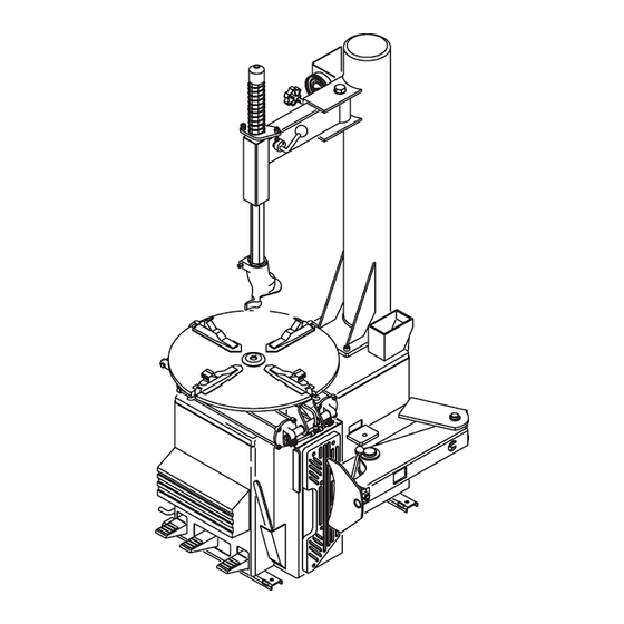
Page 14: Machine Dimentions
EHP System II / II E Tire Changer Operation Manual ® 1.3 MACHINE DIMENSIONS (Fig.2) 1.4 STANDARD ACCESSORIES (Fig.3) Fig.2 EAA0247G02A Mount/ Demount tool EAA0358G51A Inflation Gauge EAA0358G52A Air Filter and Air Lubricator Fig.3 - Page 14 -... -
Page 15: Dimensions De La Machine
EHP System II / II E Tire Changer Operation Manual ® 1.3 DIMENSIONS DE LA MACHINE (Fig.2) 1.4 ACCESSOIRES D'ORIGINE (Fig.3) EAA0247G02A Levier soulève-talon EAA0358G51A Manomètre de gonflage EAA0358G52A Groupe Filtre Lubricateur - Page 15 -... -
Page 16: Optional Accessories
EHP System II / II E Tire Changer Operation Manual ® 1.5 OPTIONAL ACCESSORIES (Fig.7) EAA0247G11A Bead depressing tool. For 20” turntable Type I only - untill December 2009 - EAA0247G07A Motorcycle Wheel Adapter Kit (4x) EAA0332G84A 8” adapter kit (4x) EAA0304G19A Light alloy rim protector (1x) For 20”... -
Page 17: Accessoires En Option
EHP System II / II E Tire Changer Operation Manual ® 1.5 ACCESSOIRES SUR DEMANDE (Fig.7) EAA0247G11A Etau de montage. Seulement pour Autocentreur 20" Type I. Jusqu’à Décembre 2009 - Adapter pour jantes moto EAA0247G07A Kit (4x) EAA0332G84A Kit adapter pour jante de 8” (4x) EAA0304G19A Protections pour jantes en alliage (1x) Seulement pour Autocentreur 20"... -
Page 18: General Cautions
EHP System II / II E Tire Changer Operation Manual ® 1.6 GENERAL CAUTIONS A. DURING USE AND MAINTENANCE OF THE MACHINE IT IS MANDATORY TO COMPLY WITH ALL LAWS AND REGULATIONS FOR ACCIDENT PREVENTION. B. THE ELECTRICAL POWER SOURCE MUST HAVE A GROUND CABLE AND THE GROUND CABLE OF THE MACHINE (YELLOW WITH GREEN) MUST BE CONNECTED TO THE GROUND CABLE OF THE POWER SOURCE. -
Page 19: Précautions Générales
EHP System II / II E Tire Changer Operation Manual ® 1.5 PRÉCAUTIONS GÉNÉRALES A. PENDANT L’UTILISATION ET L’ENTRETIEN DE LA MACHINE IL EST IMPÉRATIF DE RESPECTER TOUTES LES LOIS ET LES RÈGLES POUR LA PRÉVENTION DES ACCIDENTS. B. LA LIGNE D’ALIMENTATION ELECTRIQUE DOIT AVOIR UNE MISE A LA TERRE ET LE CABLE DE TERRE DE LA MACHINE (JAUNE ET VERT) DOIT ETRE BRANCHE AU CABLE DE TERRE DE LA LIGNE ELECTRIQUE. -
Page 20: Installation
EHP System II / II E Tire Changer Operation Manual ® ® 2.0 INSTALLATION The Tire Changer is delivered mounted to a wooden skid. Remove tire changer from its mounts carefully, taking care to avoid any back strain. Install the machine in a covered and dry place. Place Changer where proper operation will be unobstructed to all sides. -
Page 21: Montage Et Mise En Ouvre
EHP System II / II E Tire Changer Operation Manual ® ® 2.0 INSTALLATION La machine est montée sur une palette pour le transport. Enlever avec précaution le démonte-pneu de ses supports, en veillant à éviter toute traction en arrière. nstaller la machine dans un lieu couvert et sec. -
Page 22: Bead Breaker Installation
EHP System II / II E Tire Changer Operation Manual ® ® 2.2 BEAD BREAKER INSTALLATION Sometimes the side mounted Bead Breaker is shipped from the factory dismounted for a more compact shipping package. Cut the plastic tie strap which secures the Breaker Arm to the cabinet pivot. -
Page 23: Branchement Pneumatique
EHP System II / II E Tire Changer Operation Manual ® ® 2.2 FIXATION DU BRAS DETALONNEUR L’outil de décollage latéral est expédié démonté pour des raisons de volume de transport. Couper la bande en plastique qui fixe le bras de l’outil de décollage au pivot du coffret. -
Page 24: Pneumatic Hose Connection Check
EHP System II / II E Tire Changer Operation Manual ® ® After ensuring all the above proceed as follows: Connect the machine to the air supply (max. pressure of 12 bar - 170 psi) with a rubber hose able to withstand such pressure and having an internal diameter of 1/4"... -
Page 25: Contrôle Des Tuyaux Pneumatiques
EHP System II / II E Tire Changer Operation Manual ® ® Après avoir effectué tous ces contrôles, procéder comme il suit: A. Raccorder la machine au réseau d’air comprimé (réglée à la pression max. de 12 bars - 170 psi) avec un tuyau en caoutchouc (à... -
Page 26: Controls
EHP System II / II E Tire Changer Operation Manual ® 3.0 CONTROLS Fig.13 Before operating the machine, take the time to familiarize yourself with the operation and function of all the controls. Press down and release, WITH LEFT FOOT, the first pedal from the left: the jaws of the turntable will retract. -
Page 27: Commandes
EHP System II / II E Tire Changer Operation Manual ® 3.0 COMMANDES Fig.13 Avant de travailler avec la machine, s’assurer d’avoir bien compris la position et les fonctions des commandes. A Appuyer et lâcher, DU PIED GAUCHE, la première pédale de gauche: les griffes de l’autocentreur se déplacent vers le centre. - Page 28 EHP System II / II E Tire Changer Operation Manual ® When SRA is fitted. Safety Restraint Arm swings to center of the turntable. Lift upward on the restraint positioning knob to position over tire/wheel assembly for inflation, at the same time push down on the Anti-rotation Lock Arm to release lock.
- Page 29 EHP System II / II E Tire Changer Operation Manual ® Lorsque SRA est équipé. Le bras de maintien de sécurité SRA, se déplace au centre de l’autocentreur. Soulever le bouton de positionnement pour placer l’ensemble pneu/roue en vue du gonflage, en même temps appuyer sur le bras de blocage anti-rotation pour relâcher le dispositif de blocage.
-
Page 30: Mounting And Demounting Precautions
EHP System II / II E Tire Changer Operation Manual ® MOUNTING DEMOUNTING PRECAUTIONS IMPORTANT! BEFORE MOUNTING A TIRE ON A RIM, PAY ATTENTION TO THE FOLLOWING: THE RIM MUST BE CLEAN AND IN GOOD CONDITION: IF NECESSARY CLEAN AND PAINT IT AFTER REMOVING ALL WHEEL-WEIGHTS TO INCLUDE ‘TAPE WEIGHTS’... -
Page 31: Montage Et Démontage Pneus. Precautions Générales
EHP System II / II E Tire Changer Operation Manual ® MONTAGE ET DEMONTAGE PNEUS. PRECAUTIONS IMPORTANT! AVANT DE MONTER UN PNEU SUR UNE JANTE SUIVRE LES INDICATIONS SUIVANTES: . LA JANTE DOIT ÊTRE PROPRE ET EN BON ETAT: SI NÉCESSAIRE, LA NETTOYER ET LA PEINDRE APRÈS AVOIR ENLEVÉ... - Page 32 EHP System II / II E Tire Changer Operation Manual ® NOTICE! ON CHEVROLET CORVETTE WHEELS WITH THE OPTIONAL LOW PRESSURE SENSOR INSTALLED, BREAK THE BEAD AT 90 DEGREES OFFSET FROM THE VALVE STEM. DAMAGE TO THE WHEEL WILL RESULT IF THE BEAD IS BROKEN AT ANY OTHER POINT ON THE RIM.
- Page 33 EHP System II / II E Tire Changer Operation Manual ® AVIS! SUR LES ROUES DE CHEVROLET CORVETTE AYANT LE DETECTEUR DE BASSE PRESSION EN OPTION, DETALONNER A UN ANGLE DE 90 DEGRES DE LA VANNE. LA ROUE SERA ENDOMMAGEE SI ON DETALONNE EN TOUT AUTRE POINT DE LA JANTE.
-
Page 34: Mounting Tubeless Tires
EHP System II / II E Tire Changer Operation Manual ® DANGER!! Keep hands and fingers clear of mount-demount head during operation. G. Rotate the turntable clockwise (pedal down) and, at the same time, push down on the tire sidewall to move the bead into the drop center of the rim (Fig.19). -
Page 35: Montage Pneus Sans Chambre (Tubeless)
EHP System II / II E Tire Changer Operation Manual ® DANGER!! Garder les mains et les doigts à distance de sécurité de la tête de monte/ démonte pendant le fonctionnement. G. Faire tourner l’autocentreur dans le sens des aiguillesd’une montre (pédale pressé), et en même temps,appuyer sur le flanc du pneu pour maintenir le talon dansle creux (Fig.19). -
Page 36: Inflation Of Tubeless Tires
EHP System II / II E Tire Changer Operation Manual ® C. Mount the upper bead following the directions in section B. With low profile tires the bead depressor tool (option EAA0247G11A Fig.24) can help to prevent the top bead from prematurely seating during the mounting cycle. -
Page 37: Gonflage Pneus Sans Chambre (Tubeless)
EHP System II / II E Tire Changer Operation Manual ® C. Monter le talon supérieur de la même façon. Pour les pneus taille baisse, utiliser l’étau de montage en option (#EAA0247G11A Fig. 24). NOTE: S’assurer d’enlever l’étau de montage avant que il complète un tour et impacts l’outil. -
Page 38: To Utilize The Bead Seater
EHP System II / II E Tire Changer Operation Manual ® Due to unusual configurations or the stacking of tires the inflation process may be difficult. To assist with this problem the EHP Tire Changer machine are equipped with bead seater jets integrated into the table top. -
Page 39: Utiliser Le Dispositif D'étalonnage Du Pneu
EHP System II / II E Tire Changer Operation Manual ® Le processus de gonflage peut s’avérer difficile en présence de configurations insolites ou à cause de mauvaises conditions de stockage. Pour répondre à ces problèmes le modèle EHP est équipé de jets pour le talonnage qui sont insérés dans l’autocentreur. -
Page 40: Demounting Tube-Type Tires
EHP System II / II E Tire Changer Operation Manual ® 5.0 DEMOUNTING TUBE-TYPE TIRES A. For breaking the bead operate as described for the tubeless tires in Point A of Chapter 4.1. to 4.1 (F). In this case the valve is part of the tube. NOTICE! BE CAREFUL NOT TO DAMAGE THE TUBE DURING THE BEAD-BREAKING OPERATION. -
Page 41: Démontage Pneus Avec Chambre
EHP System II / II E Tire Changer Operation Manual ® 5.0 DÉMONTAGE PNEUS AVEC CHAMBRE A. Pour le démontage opérer comme décrit pour les pneus sans chambre au Chapitre 4.1 A to 4.1.F. Dans ce cas la vanne ne peut pas être remplacée car elle est unie à... -
Page 42: Inflating Tube-Type Tires
EHP System II / II E Tire Changer Operation Manual ® 5.2 INFLATING TUBE-TYPE TIRES To inflate the tire unlock the rim and start inflating while pressing the valve towards the inside. This is necessary to avoid air pockets forming between tube and tire (Fig. 29). -
Page 43: Gonflage Pneus Avec Chambre
EHP System II / II E Tire Changer Operation Manual ® 5.2 GONFLAGE PNEUS AVEC CHAMBRE Débloquer la jante et commencer à gonfler le pneu en poussant la vanne vers l'intérieur pour éviter la formation de poches d'air entre la chambre à air et l'enveloppe (Fig.29). -
Page 44: Maintenance
EHP System II / II E Tire Changer Operation Manual ® 7.0 MAINTENANCE WARNING! BEFORE STARTING ANY MAINTENANCE OPERATION ENSURE THAT THE MACHINE IS DISCONNECTED FROM THE AIR AND ELECTRIC SUPPLY. A. Periodically clean the vertical hexagonal rod with nonflammable liquid detergent. After this immediately lubricate with a light lubricating oil (Fig.30). -
Page 45: Entretien
EHP System II / II E Tire Changer Operation Manual ® 6.0 ENTRETIEN AVERTISSEMENT ! AVANT DE COMMENCER TOUTE OPÉRATION D’ENTRETIEN ET DE RÉPARATION DÉBRANCHER LA MACHINE DU RÉSEAU ÉLECTRIQUE ET DE L’AIR COMPRIMÉ. A. Nettoyer périodiquement la tige hexagonale avec un détergent liquide non inflammable. -
Page 46: Moving The Machine
EHP System II / II E Tire Changer Operation Manual ® 8.0 MOVING THE MACHINE In case the machine is to be moved from one working place to another, proceed as follows: Disconnect the machine from the air and electric supply. Remove from top of the cabinet and turntable all objects that may fall during displacement and create hazard. -
Page 47: Mise De Côté
EHP System II / II E Tire Changer Operation Manual ® 8.0 DÉPLACEMENT Si la machine doit être déplacée d’une position à une autre, procéder suivant les indications ci-dessous: Debrancher les sources d’alimentation électrique et pneumatique. Enlever du plateau de la machine les éventuels dispositifs ou les pièces qui pourraient tomber pendant le déplacement et causer ainsi des dangers. -
Page 48: Mh 310 Bead Assist Attachment
The BEAD ASSIST can be used only in conjunction with John Bean EHP Series Tire Changers. The MH 310 should be used only as intended and instructed so within its manual. - Page 49 EHP System II / II E Tire Changer Operation Manual ® 10 DISPOSITIF DETALONNEUR SUPPLÉMENTAIRES MH 310 POUR RETROINSTALLATION DE L’UNITE’ SUR LE TERRAIN 1.1 INTRODUCTION Les presse-talons modèles MH 310 sont des dispositifs destinés à faciliter le montage et le démontage de pneus pour voiture.
- Page 50 EHP System II / II E Tire Changer Operation Manual ® 2.0 HANDLING INSTRUCTIONS ALWAYS WEAR GLOVES WHEN UNCRATING THE MA- CHINE TO PREVENT SCRATCHES OR ABRASIONS DUE TO CONTACT WITH PACKING MATERIALS. The shipping box is mounted in a steady wooden pallet. The machine should be transported only with an appropri- ate lifting device (fork lift) Fig.1.
- Page 51 EHP System II / II E Tire Changer Operation Manual ® 2.0 MANIPULATION METTRE TOUJOURS DES GANTS PENDANT LEDÉBALLAGE POUR ÉVITER DES GRIFFURES OUDES ÉGRATIGNURES DUES AU CONTACT AVECLE MATÉRIEL DE L’EMBALLAGE. Cette boîte est montée sur une palette pour le transport. Le transport de la machine emballée doit être effectué...
- Page 52 Notice: The information contained in this document is subject to change without notice. John Bean Company makes no warranty with regard to this material. John Bean Company shall not be liable for errors contained herein or for incidental consequential damages in connection with furnishings, perfor- mance, or use of this material.
Need help?
Do you have a question about the EHP System Series and is the answer not in the manual?
Questions and answers