Table of Contents
Advertisement
Available languages
Available languages
Quick Links
Advertisement
Table of Contents

Related Manuals for John Bean EHP System IV-E


Summary of Contents for John Bean EHP System IV-E
- Page 1 Manual do Operador Manual do Operador EHP System IV-E...
- Page 2 SAFETY INFORMATION For your safety, read this manual thoroughly before operating the Tire Changer This tire changer is intended for use by properly trained automotive technicians. The safety mes- sages presented in this section and throughout the manual are reminders to the operator to exer- cise extreme caution when servicing tires with these products.
- Page 3 IMPORTANT SAFETY INSTRUCTIONS When using this equipment, basic safety precautions should always be followed, including the following: Read all instructions. Do not operate equipment with a damaged power cord or if the equipment has been damaged - until it has been examined by a qualifi ed authorized service technician. If an extension cord is used, a cord with a current rating equal to or more than that of the machine should be used.
-
Page 4: Table Of Contents
TABLE OF CONTENTS: English Table Of Contents ...........................Page 4 SAFETY INFORMATIONS .......................Page 6 DANGER ............................Page 7 INSTRUCTIONS: Safety Label Meanings ..................Page 8 Introduction ............................Page 10 Nomenclature ..........................Page 10 Specifi cations ..........................Page 12 Machine Dimentions ........................Page 12 Accessories ..........................Page 12 General Cautions ...........................Page 14 1.5.1 Precautions ...........................Page 14 Installation ............................Page 16 2.0.1 Models with SRA attached (Optional part) ..................Page 16... -
Page 5: Sommaire
EC DECLARATION (Original document contained in Spare Parts Booklet) DECLARATION CE (Le document original fi gurant dans le Liste des pièces détachées) CE KONFORMITÄTSERKLÄRUNG (Originaldokument in der Ersatzteilliste enthaltenen) DICHIARAZIONE CE ( Originale contenuta nel Libretto Ricambi) DECLARACIÓN CE ( El original se encuentra en tabla de repuestos) DECLARAÇÃO CE ( O original está... -
Page 6: Safety Informations
SAFETY INFORMATION INFORMATIONS DE SÉCURITÉ For your safety, read this manual thoroughly Pour votre sécurité, avant d’actionner le démonte- pneu lire complètement le EHP System IV E before operating the EHP System IV E Tire présent manuel Changer The EHP System Tire Changers are Le démonte-pneu électro-pneumatique intended for use by properly trained EHP System... -
Page 7: Danger
Il n’est pas possible d’utiliser ensemble des Tires and Rims that are not the same pneus et des jantes de diamètre différent. diameter are mismatched. Ne JAMAIS essayer de monter ou de gonfl er • NEVER attempt to mount or infl ate any tire •... -
Page 8: Instructions: Safety Label Meanings
INSTRUCTIONS: Safety Label Meanings IMPORTANT!! SAVE THESE INSTRUCTIONS Overinfl ated tires or tires mounted on the wrong sized rims can explode producing hazardous fl ying debris. • Read and understand the operation instructions before using this tire changer. • Never mount tire on rim with different sized diameter. •... - Page 9 INSTRUCTIONS : Lecture de la plaque de sécurité IMPORTANT!! CONSERVER LES PRESENTES INSTRUCTIONS Les pneus surgonfl és ou les pneus montés sur des jantes de taille non appropriée peuvent exploser et projeter des fragments. • Lire et comprendre le manuel d’utilisation avec d’utiliser ce démonte-pneu. •...
-
Page 10: Introduction
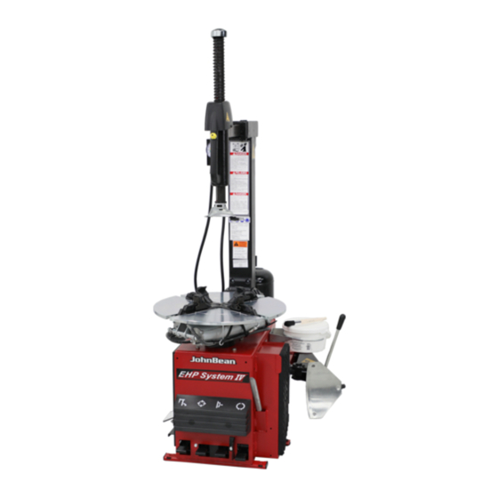
1.0 Introduction Congratulations on purchasing the “EHP System IV” electric/air tire changer. This tire changer is designed for ease of operation, safe handling of rims, reliability and speed. This combination of features means more profi t and added versatility for your shop, enabling you to work with aluminium or magnesium alloy wheels without damaging customer’s rims. -
Page 11: Introduction
1.0 Introduction Félicitations pour avoir acheté le démonte-pneu électro-pneumatique “EHP System IV”. Cet ensemble de caractéristiques signifie pour votre entreprise des profi ts plus élevés ainsi qu’une polyvalence majeure car il vous permet de travailler sur des roues en alliage aluminium ou magnésium sans endommager la jante. -
Page 12: Specifi Cations
1.2 Specifi cations Electric-air tire changer for car, light commercial vehicle and motorcycle tires designed for one-piece rims. Operation temperature range +41/+122 F (+5/50 °C) Shipping Weight lbs 610 (227 kg) Air pressure required psi 110-170 (8-12 bar) Bead breaker force lbs 3300 (15 kN) Electrical Requirements: 115 V AC, 60Hz Single... -
Page 13: Caractéristiques Techniques
1.2 Caractéristiques techniques Démonte-pneus électro-pneuma-tique pour roues de voiture, de fourgon et de moto avec pneus montés sur jantes à base creuse. Plage de températures +41/+122 F (+5/50 °C) Poids d’expédition lbs 610 (227 kg) Pression air comprimé psi 110-170 (8-12 bar) Force détalonneur lbs 3300 (15 kN) Conditions d’alimentation:... -
Page 14: General Cautions
1.5 General Cautions A. DURING USE AND MAINTENANCE OF THE MACHINE IT IS MANDATORY TO COMPLY WITH ALL LAWS AND REGULATIONS FOR ACCIDENT PREVENTION. B. THE ELECTRICAL POWER SOURCE MUST HAVE A GROUND CABLE AND THE GROUND CABLE OF THE MACHINE (YELLOW WITH GREEN) MUST BE CONNECTED TO THE GROUND CABLE OF THE POWER SOURCE. -
Page 15: Précautions Générales
1.5 Précautions générales A. PENDANT L’UTILISATION ET L’ENTRETIEN DE LA MACHINE IL EST IMPÉRATIF DE RESPECTER TOUTES LES LOIS ET LES RÈGLES POUR LA PRÉVENTION DES ACCIDENTS. B. LA LIGNE D’ALIMENTATION ELECTRIQUE DOIT AVOIR UNE MISE A LA TERRE ET LE CABLE DE TERRE DE LA MACHINE (JAUNE ET VERT) DOIT ETRE BRANCHE AU CABLE DE TERRE DE LA LIGNE ELECTRIQUE. -
Page 16: Installation
2.0 INSTALLATION 2.0.1 MODELS WITH SRA ATTACHED (OPTIONAL PART) Once placed in the desired location the tire changer must be bolted to the fl oor using anchors supplyed with the machines with Safety Restraint Arm SRA. Concrete must be steel mesh reinforced. Tire Changer must be anchored to concrete fl... -
Page 17: Intallation
2.0 INSTALLATION 2.0.1 MODELES AVEC SRA JOINTE (OPTIONELLE). Une fois placé à l’endroit désiré le démontepneu doit être boulonné au plancher en utilisant des ancres supplied avec les machines avec le bras de retenue de sécurité SRA. Le béton doit être un treillis en acier renforcé. Le démonte-pneu doit être fi... -
Page 18: Electrical Installation
Tilt the column backwards. Pull the rod “E” of the tilting cylinder and connect it to the column with the pin “F”. Apply N°243 Loctite to the grub screw “H” and tighten with a tightening torque of 11 Nm. Fix the manometer ‘S’ with the available screws, as shown in Fig. -
Page 19: Branchement Eléctrtique
Déplacer la potence en arrière. Tirer la tige “E” du piston et l’assembler à la potence avec le goujon “F”. Appliquer du FreinFilet n°243 à la vis “H” et serrer à un couple de 11 Nm. Fixez le manomètre ‘S’ avec les vis prévues à cet effet comme illustré... -
Page 20: Bead Breaker Installation
2.2 BEAD BREAKER INSTALLATION Sometimes the side mounted Bead Breaker is shipped from the factory dismounted for a more compact shipping package. A. Cut the plastic tie strap which secures the Breaker Arm to the cabinet pivot. B. Place the bead breaker arm (1,Fig.2.0-2) inside arm support (4). -
Page 21: Fixation Du Bras Detalonneur
2.2 FIXATION DU BRAS DETALONNEUR L’outil de décollage latéral est expédié démonté pour des raisons de volume de transport. A. Couper la bande en plastique qui fi xe le bras de l’outil de décollage au pivot du coffret. B. Positionner le bras détalonneur (1,Fig.2.0-2) dans son support (4). -
Page 22: Pneumatic Hose Connection Check
Connect the machine to the air supply (max. pressure of 12 bar - 170 psi) with a rubber hose able to withstand such pressure and having an internal diameter of 1/4” (8 mm) (Fig. 2.0-3). WARNING! BEFORE CONNECTING THE MACHINE TO THE AIR SUPPLY BE SURE ALL PERSONNEL ARE CLEAR OF THE MACHINE AND THAT NOTHING IS LEFT ON THE TURNTABLE AREA (TOOLS) -
Page 23: Contrôle Des Tuyaux Pneumatiques
Raccorder la machine au réseau d’air comprimé (réglée à la pression max. de 12 bars - 170 psi) avec un tuyau en caoutchouc (à même de supporter cette pression et de 1/4” (8 mm) de diamètre intérieur (Fig. 2.0-3). AVERTISSEMENT ! AVANT DE RELIER LA MACHINE AU RÉSEAU DE L’AIR COMPRIMÉ, CONTRÔLER QUE RIEN NE SOIT LAISSÉ... -
Page 24: Controls
3.0 Controls Before operating the machine, ensure that you have well understood the operation and function of all the controls (Fig.3.0-1). A. Press down and release, WITH LEFT FOOT, the fi rst pedal from the left: the column tilts backwards. Do it again: the column tilts forward. -
Page 25: Commandes
3.0 Commandes Avant de travailler avec la machine, s’assurer d’avoir bien compris la position et les fonctions des commandes (Fig3.0-1). A. Appuyer et lâcher, DU PIED GAUCHE, la première pédale de gauche: la potence se déplace en arrière. Appuyer de nouveau: la potence se déplace en avant. AVERTISSEMENT : DANGER D’ENCRASEMENT DU CORPS BLOQUER LES JANTES EN ALLIAGE PAR... - Page 26 ATTENTION! DANGER OF HAND CRUSHING Press bead seater/infl ator pedal on left side of the machine down (1, Fig. 3.0-3): air will come from infl ation hose end. On model with bead seater BS: Press bead seater/infl ator pedal on left side of the machine half way down (1, Fig.
- Page 27 ATTENTION ! DANGER D’ENCRASSEMENT DES MAINS Appuyer sur la pédale du gonfl eur (1, Fig. 3.0-3) : l’air sort de l’extrémité du tuyau de gonfl age. Dans le modèle avec gonfl eur tubeless : Appuyer sur la pédale du gonfl eur jusqu’à mi-course (1, Fig.
-
Page 28: Mounting And Demounting Precautions
4.0 Mounting And Demounting. Precautions IMPORTANT! BEFORE MOUNTING A TIRE ON A RIM ENSURE THE FOLLOWING RULES ARE OBSERVED: A. THE RIM MUST BE CLEAN AND IN GOOD CONDITION: IF NECESSARY CLEAN AND PAINT AFTER REMOVING ALL WHEEL-WEIGHTS INCLUDING ‘TAPE WEIGHTS’ INSIDE THE RIM. B. -
Page 29: Montage Et Démontage Pneus. Precautions Générales
4.0 Montage et démontage pneus. Précautions générales IMPORTANT! AVANT DE MONTER UN PNEU SUR UNE JANTE SUIVRE LES INDICATIONS SUIVANTES: A. LA JANTE DOIT ÊTRE PROPRE ET EN BON ETAT: SI NÉCESSAIRE, LA NETTOYER ET LA PEINDRE APRÈS AVOIR ENLEVÉ TOUTES LES MASSES Y COMPRIS LES MASSES COLLÉES ÉVENTUELLEMENT APPLIQUÉES À... - Page 30 Pay extra attention during this operation as it easy to mistakenly keep your foot on the bead breaker pedal too long. This could result in immediate bead damage. WARNING ON CHEVROLET CORVETTE WHEELS WITH THE OPTIONAL LOW PRESSURE SENSOR INSTALLED, BREAK THE BEAD AT 90 DEGREES OFFSET FROM THE VALVE STEM.
- Page 31 pneu de 90 degrés et de répéter la procédure ci-dessus pour sortir tous les talons. Prendre garde de ne pas laisser le pied trop longtemps sur la pédale de détalonnage pendant cette opération. Cela pourrait endommager le talon. AVERTISSEMENT ! SUR LES ROUES DE CHEVROLET CORVETTE AYANT LE DETECTEUR DE BASSE PRESSION EN OPTION, DETALONNER A UN ANGLE DE...
- Page 32 NOTE: O N C E T H E M O U N T / D E M O U N T H E A D I S POSITIONED PROPERLY, IDENTICAL WHEELS MAY BE CHANGED WITHOUT HAVING TO RESET THE HEAD. F.
- Page 33 NOTE: QUAND L’OUTIL DE MONTAGE/DÉMONTAGE A ÉTÉ CORRECTEMENT POSITIONNÉ, LES ROUES IDENTIQUES PEUVENT ÊTRE MONTÉES SANS DEVOIR RÉGLER L’OUTIL DE NOUVEAU. F. Introduire le levier pour soulever l’enveloppe en- dessous du talon et au-dessus du support de l’outil. Soulever le talon sur la languette de montage. Pour rendre l’opération plus facile, appuyer, de la main gauche, sur le flanc du pneu dans une position opposée à...
-
Page 34: Mounting Tubeless Tires
4.2 Mounting tubeless tires A. Lubricate the entire rim surface (Fig. 4.2-1). Lubricate both beads, inside and outside, (Fig. 4.2-2). WARNING LIBERAL LUBRICATION OF THE TIRE AND RIM IS NECESSARY TO MOUNT TIRE CENTERING CORRECTLY AND GET A PROPER ON THE RIM. -
Page 35: Montage Pneus Sans Chambre (Tubeless)
4.2 Montage pneus sans chambre (tubeless) A. Lubrifi er toute la surface de la jante (Fig. 4.2-1). Lubrifi er les deux talons du pneu à l’intérieur et à l’extérieur avec un lubrifi ant pour pneus (Fig. 4.2-2). AVERTISSEMENT ! UNE LUBRIFICATION ABONDANTE EST NECÉSSAIRE POUR MONTER LE PNEU CORRECTEMENT ET OBTENIR UN BON CENTRAGE SUR LA JANTE. -
Page 36: Infl Ation Of Tubeless Tires
4.3 Infl ation of tubeless tires Make sure that both beads are properly lubricated. WARNING: BEAD SEATING IS THE MOST DANGEROUS PART OF MOUNTING A TIRE. IT IS POSSIBLE TO MOUNT TIRES THAT ARE 1/2” SMALLER IN DIAMETER THAN THE RIM THEY ARE MOUNTED ON. -
Page 37: Gonfl Age Pneus Sans Chambre
4.3 Gonfl age pneus sans chambre (tubeless) S’assurer que les deux talons soient bien lubrifi és AVERTISSEMENT ! LA MISE EN PLACE DU TALON EST LA PHASE LA PLUS DANGEREUSE DU MONTAGE D’UN PNEU. IL EST POSSIBLE DE MONTER DES PNEUS DE 1/2”... -
Page 38: Mounting And Demounting Motorcycle Tires
4.4 Mounting and Demounting Motorcycle Tires To mount and demount motorcycle, motor scooter or ATV tires it is necessary to utilize the optional adaptors (4 piece EAA0247G07A or EAA0332G84A) and the small-wheel bead breaker blade. The bead breaking, mounting and demounting technique is the same as per car tires. -
Page 39: Montage Et Démontage Pneus Moto
4.4 Montage et Démontage Pneus Moto Pour opérer sur les pneus pour motocyclette, moto- scooters/ATV il faut monter les adaptateurs à prise rapide sur les griffes de l’autocentreur (4 pièces EAA0247G07A ou EAA0332G84A) et la petite Palette Detalloneur. La technique de détalonnage, de montage et de démontage est la même que pour les pneus pour auto. -
Page 40: Demounting Tube-Type Tires
5.0 Demounting tube-type tires A. For breaking the bead operate as described for the tubeless tires in § 4.1.A to 4.1.F. In this case, the valve is part of the tube WARNING: BE CAREFUL NOT TO DAMAGE THE TUBE DURING THE BEAD-BREAKING OPERATION. -
Page 41: Démontage Pneus Avec Chambre
5.0 Démontage pneus avec chambre A. Pour le démontage opérer comme décrit pour les pneus sans chambre au § 4.1 A to 4.1.F. Dans ce cas la vanne ne peut pas être remplacée car elle est unie à la chambre à air. AVERTISSEMENT ! NE PAS ENDOMMAGER LA CHAMBRE À... -
Page 42: Maintenance
6.0 maintenance WARNING BEFORE ATTEMPING ANY MAINTENANCE OR REPAIRS THE MACHINE MUST BE DISCONNECTED FROM THE AIR AND ELECTRIC SUPPLY. A. Periodically clean the vertical hexagonal rod with nonfl ammable liquid detergent. Lubricate with oil (Fig. 5.4). B. Periodically clean all moving metal parts and lubricate with oil. -
Page 43: Entretien
6.0 Entretien AVERTISSEMENT ! AVANT DE COMMENCER TOUTE OPÉRATION D’ENTRETIEN ET DE RÉPARATION DÉBRANCHER LA MACHINE DU RÉSEAU ÉLECTRIQUE ET DE L’AIR COMPRIMÉ. A. Nettoyer périodiquement la tige hexagonale avec un détergent liquide non infl ammable. Lubrifi er avec de l’huile (Fig. 5.4). B. -
Page 44: Putting The Machine Out Of Service
7.0 Putting the machine out of service In case the machine is not be used for a long period of time (6 months or more) it is necessary to disconnect air and power discharge the bead seater tank (if provided), service, protect all parts that may be damaged from environmental , protect the air hoses that may be damaged... -
Page 45: Vente De La Machine
7.0 Mise de côté En cas de mise de côté de la machine pendant longtemps (6 mois) il est nécessaire de déconnecter les sources d’alimentation, de vider le réservoir, de protéger toutes les pièces qui pourraient être endommagées, de protèger les tuyaux pneumatiques qui pourraient être endommagés par le séchage. -
Page 46: Mh 320 Pro Bead Assist Attachment
The BEAD ASSIST can be used only in conjunction with John Bean EHP Series Tire Changers. The MH 320 PRO should be used only as intended and instructed so within its manual. -
Page 47: Dispositif Detalonneur Supplémentaires Mh 320 Pro
Pour pouvoir être utilisé, cet accessoire doit être monté exclusivement sur les modèles de démonte- pneus John Bean EHP Series. MH 320 PRO devrait être utilisé comme prévu et selon les informations de son manuel. - Page 48 10.3 HANDLING INSTRUCTIONS ALWAYS WEAR GLOVES WHEN UNCRATING THE MACHINE TO PREVENT SCRATCHES OR ABRASIONS DUE TO CONTACT WITH PACKING MATERIALS. The shipping box is mounted in a steady wooden pal- let. The machine should be transported only with an appropriate lifting device (fork lift) Fig.1.
- Page 49 10.3 MANIPULATION METTRE TOUJOURS DES GANTS PENDANT LEDÉBALLAGE POUR ÉVITER DES GRIFFURES OUDES ÉGRATIGNURES DUES AU CONTACT AVECLE MATÉRIEL DE L’EMBALLAGE. Cette boîte est montée sur une palette pour le transport. Le transport de la machine emballée doit être effectué avec un dispositif de levage spécial (chariot élévateur) (Fig.
- Page 52 309 Exchange Ave. 309 Exchange Ave. Conway, AR 72032 Conway, AR 72032 Ph: 501-450-1500 Ph: 501-450-1500 Fax: 501-450-2085 Fax: 501-450-2085 Notice: The information contained in this document is subject to change without notice. Snap-on Equipment makes Notice: The information contained in this document is subject to change without notice. Snap-on Equipment makes no warranty with regard to present documentation.
Need help?
Do you have a question about the EHP System IV-E and is the answer not in the manual?
Questions and answers