
Related Manuals for John Bean EHP System I


Summary of Contents for John Bean EHP System I
- Page 1 EHP System I, II and III High Performance Tire Changers Operation Instructions Form 5843 For Reference Only For Current Info See Equiserv.com...
- Page 2 (BLANK PAGE) For Reference Only For Current Info See Equiserv.com...
- Page 3 COPYRIGHT NOTICE The information contained in this document is property of John Bean, division of Snap-on Incorporated. It or any of the information contained within shall not be used, copied, or reproduced without express written consent of John Bean or its holding company.
- Page 4 (BLANK PAGE) For Reference Only For Current Info See Equiserv.com...
-
Page 5: Safety Statements
EHP Series Operation Instructions SAFETY INFORMATION For your safety, read this manual thoroughly before operating the EHP Series Tire Changer The EHP Series Tire Changers are intended for use by properly trained automotive technicians. The safety messages presented in this section and throughout the manual are reminders to the operator to exercise extreme care when changing tires with these products. - Page 6 SAFETY INSTRUCTIONS IMPORTANT!! SAVE THESE INSTRUCTIONS Overinflated tires or rims mounted on the wrong sized rims can explode producing hazardous flying debris. • • • • • Read Operator’s Manual before using this Tire Changer. • • • • • Never mount tire on rim with different sized diameter.
- Page 7 EHP Series Operation Instructions Risk of crushing. Stand clear of bead breaker arm during operation. Warning ! • • • • • Read and understand the operation instructions before using this tire changer. • • • • • Become familiar with all controls before proceeding with operation. •...
- Page 8 Tires and Rims that are not the same diameter are mismatched. • • • • • NEVER attempt to mount or inflate any tire and rim that are mismatched. • • • • • ALWAYS check to see that tire and rim diameters are the same. A mismatched tire and rim will explode causing death or serious personal injury Over-pressurized tires can explode causing flying debris.
-
Page 9: Table Of Contents
EHP Series Operation Instructions TABLE OF CONTENTS Safety Statements Page 5-8 Table of Contents Page 1.0 Introduction Page 10 1.1 Specifications and Features Page 10 1.2 Nomenclature Page 12 1.3 Dimensions of the Machine Page 12 1.4 Standard Accessories Page 12 1.5 Optional Accessories Page 13 1.6 General Precautions... -
Page 10: Introduction
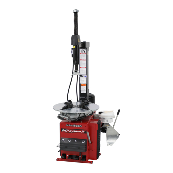
Swing Arm INTRODUCTION Detail Jaw and Air Jet Detail Congratulations on purchasing the JBC EHP Series elec- tric/air tire changer. This tire changer is designed for ease of operation, safe handling of rims, reliability and speed. This combination of features means more profit and added versatility for your shop, enabling you to work with aluminum or magnesium alloy wheels without dam- aging customer’s rims. - Page 11 EHP Series Operation Instructions TURNTABLE & CABINET FEATURES SAFETY RESTRAINT ARM (Optional) TIRE/RIM ASSEMBLY RESTRAINT - Safety Restraint Arm TURNTABLE PLATFORM - Provides easier access to tires positively restrains tire and rim assembly to the tire machine during lower bead during the tire changing process. the inflation process reducing potential for injury caused by the INTEGRATED BEAD SEATING JETS - Air inflation jets are...
-
Page 12: Dimensions Of The Machine
MACHINE DIMENSIONS - System I STANDARD ACCESSORIES 87111 - Mount /Demount Tool (Fig.3) Figure 3 Inflation Guage is mounted on the Inflation Tank Col- umn. (Not shown) Air Filter and Air Lubricator, (Fig.4) MACHINE DIMENSIONS - System II and III Figure 4 Incoming Air Pressure Gauge Located on the air filter and the air lubricator... -
Page 13: Optional Accessories
EHP Series Operation Instructions EAA0332G84A OPTIONAL ACCESSORIES 87436 - 8" Wheel Adapter (Fig.5) ST4028566 or 87435 - Motorcycle Adapter (Fig.5) EAA0304G23A Figure 6 66735 - Bead Holding Clamp (Fig.7) Figure 5 Figure 7 - Page 13 - For Reference Only For Current Info See Equiserv.com... -
Page 14: General Precautions
GENERAL CAUTIONS ELECTRICAL INSTALLATION A. DURING THE USE AND MAINTENANCE OF THE MA- CHINE IT IS MANDATORY TO COMPLY WITH ALL LAWS AND REGULATIONS FOR ACCIDENT PREVENTION. BUILDING ELECTRICAL INSTALLATION MUST BE MADE BY A LICENSED ELECTRICIAN. B. THE ELECTRICAL POWER SOURCE MUST HAVE A GROUND CABLE AND THE GROUND CABLE OF THE Check that the electrical specifications of the power MACHINE MUST BE CONNECTED TO THE GROUND... -
Page 15: Air Installation
EHP Series Operation Instructions 2.2 BEAD BREAKER INSTALLATION WARNING! The side mounted Bead Breaker is shipped from the BEFORE CONNECTING THE factory dismounted for a more compact shipping pack- MACHINE TO THE AIR SUP- age. PLY BE SURE ALL PERSON- NEL ARE CLEAR OF THE MA- CHINE AND NO ITEMS ARE A. -
Page 16: Controls
CONTROLS 541a 542a Press down the first pedal (3) from the right: the turntable turns clockwise. Placing your foot under the pedal and lift, the turntable turns counterclock- wise. Lower the Lock Lever (4 ) to unlock the vertical slide, lift the Lock Lever to lock. -
Page 17: Mounting And Demounting-Precautions
EHP Series Operation Instructions Pay extra attention during this operation as it easy to 4.0 MOUNTING AND DEMOUNTING PRECAUTIONS mistakenly keep your foot on the bead breaking pedal too long. This could potentially result in bead or rim IMPORTANT! damage BEFORE MOUNTING A TIRE ON A RIM, PAY ATTENTION TO THE FOLLOWING: A. - Page 18 D. Liberally lubricate both beads. Place the wheel WITH DROP CENTER UP (Fig.13a) on the turntable, and clamp in position. Hold the tire and wheel down while clamping. 1/16” Fig.14 NOTE: EVERY MACHINE IS EQUIPPED WITH SEVERAL RE- Fig.13 Fig. 13a PLACEMENT PLASTIC INSERTS (INSIDE STANDARD EQUIPMENT PACK).
- Page 19 EHP Series Operation Instructions Fig.15 G. Rotate the turntable clockwise (pedal down) and, at Fig.17 the same time, push down on the tire sidewall to move the bead into the drop center of the rim (Fig.16). Fig.16 H. Repeat the process for removing the lower bead. This time, lift the bead opposite to the mount/demount head to keep it in the drop center (Fig.17).
-
Page 20: Mounting Tubeless Tires
4.2 MOUNTING TUBELESS TIRES NOTICE! THESE LUBRICATION OPERATIONS ARE NECESSARY A. Clean entire rim surface (Fig.18). TO MOUNT THE TIRE CORRECTLY AND GET A PROPER CENTERING ON THE RIM. BE SURE YOU ARE USING APPROVED LUBRICANT ONLY. DANGER!! Keep hands Fig.18 and fingers clear of mount-demount head... -
Page 21: Inflating Tubeless Tires
EHP Series Operation Instructions NOTICE! 4.3 INFLATION OF TUBELESS TIRES. SOME TIRES HAVE A COLOR DOT THAT IS TO BE KEPT ON THE OUTSIDE OF THE WHEEL AND IS TO BE ALIGNED Make sure that both beads are properly lubricated. WITH THE VALVE STEM. - Page 22 C. Connect the inflation hose to the valve stem. D. Lift the tire with both hands so that the upper bead is sealed to the rim edge (Fig.21). NEVER STAND OVER TIRE WHEN ATTEMPTING TO SEAT BEADS OR DURING INFLATION Fig.22 E.
-
Page 23: Demounting Tube Type Tires
EHP Series Operation Instructions 5.0 DEMOUNTING TUBE-TYPE TIRES C. Inflate the tube slightly: if held with the index finger it should bend a little (Fig.24). A. For breaking the bead operate as described for the tubeless tires in section 4.1.A to 4.1.F. In this case the valve is part of the tube. -
Page 24: Inflating Tube Type Tires
5.2 INFLATING TUBE-TYPE TIRES. Make sure that both beads are properly lubricated. BEAD SEATING IS THE MOST DANGEROUS PART OF MOUNTING A TIRE. NEVER STAND OVER TIRE WHEN ATTEMPTING TO SEAT BEADS OR DURING INFALATION IT IS POSSIBLE TO MOUNT TIRES THAT ARE 1/2" SMALLER IN DIAMETER THAN THE RIM THAT THEY ARE MOUNTED ON. -
Page 25: Maintenance
EHP Series Operation Instructions 7.0 MAINTENANCE D. Inspect and replace as necessary the plastic mount/ demount head insert. The insert is held in place by a small roll pin. Drive the pin out with a punch, replace after new insert is installed. BEFORE STARTING ANY MAINTENANCE OPERATION E. - Page 26 (BLANK PAGE) For Reference Only For Current Info See Equiserv.com...
- Page 27 (BLANK PAGE) For Reference Only For Current Info See Equiserv.com...
- Page 28 Notice: The information contained in this document is subject to change without notice. John Bean makes no warranty with regard to this material. John Bean shall not be liable for errors contained herein or for incidental consequential damages in connection with furnishings, performance, or use of this material.
Need help?
Do you have a question about the EHP System I and is the answer not in the manual?
Questions and answers