Table of Contents
Advertisement
Quick Links
RX on Ground
Contents
I. Disclaimer ................................................................................................................................................................ 2nd
II. Precautions for integration .....................................................................................................................................2nd
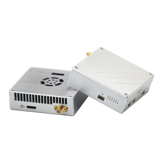
III. List of in-box items ................................................................................................................................................. 4th
IV. Interface Definition .................................................................................................................................................5th
4.1. TX and Rx Interface Definition(Tx and Rx have same interface definition) ................................................. 5th
4.1.1. Power Interface ................................................................................................................................. 5th
4.1.3. How to connect with Auto Pilot system on board by TTL cable .......................................................5th
4.1.4. RS232 Interface ................................................................................................................................. 6th
4.1.5.How to connect with Auto Pilot system on board by RS232 cable ................................................... 6th
4.1.6. RF and HDMI Interface ...................................................................................................................... 6th
4.1.7. S2 Interface ........................................................................................................................................7th
4.1.8. ETH .....................................................................................................................................................7th
4.1.9. How connect Rx with GCS by TTL to USB Cable ................................................................................8th
5.1. Make TX and RX and accessories ready. ...................................................................................................... 8th
5.2. Connection ................................................................................................................................................... 9th
5.3. Power on .......................................................................................................................................................9th
5.4. The status of all indicators during starting ...................................................................................................9th
www.iwavecomms.com
FIM-2430 User Manual
TX on Board
1st
Advertisement
Table of Contents

Related Manuals for iWave FIM-2430


Summary of Contents for iWave FIM-2430
-
Page 1: Table Of Contents
FIM-2430 User Manual RX on Ground TX on Board Contents I. Disclaimer ................................2nd II. Precautions for integration .............................2nd III. List of in-box items ..............................4th IV. Interface Definition ..............................5th 4.1. TX and Rx Interface Definition(Tx and Rx have same interface definition) ..........5th 4.1.1. -
Page 2: Disclaimer
The Chinese version shall prevail in Chinese mainland, while the English version shall prevail in other regions. Thank you for purchasing IWAVE FIM-2430. Please use FIM-2430 according to local radio regulations. Before using, please carefully read this disclaimer. Once the product is used, all the contents of the disclaimer will be regarded recognized and accepted. - Page 3 10) Before using, please make sure all cables are in good connection and all components can work properly. 11) After starting the product, the self-test indicators of FIM-2430 will continuously blink for 30s and then keep bright. Only after the video from the camera shown on the display, then you can confirm that the device work properly now.
-
Page 4: List Of In-Box Items
Notes: Improper operation of FIM-2430 may cause personal injury or damage to properties. Please pay high attention to operation safety. III. List of in-box items On board x1 Ground terminal x1 On board antenna x1 Ground antenna x1 DC power cable x2... -
Page 5: Interface Definition
IV. Interface Definition 4.1. TX and Rx Interface Definition(Tx and Rx have same interface definition) 4.1.1. Power Interface Power on/off: Pull - type switch Power Connector: XT30PW-F(Female) Power Cable: One end XT30PW(Male), the other end DC(female) 4.1.2. S1 Serial Port : 5P GH with lock socket(GH 1.25mm, we only use 4P) GH 5P Signal Definition... -
Page 6: Rs232 Interface
4.1.4. RS232 Interface RS232: 3p GH with lock socket(GH 1.25mm) GH 3P Signal Definition 4.1.5.How to connect with Auto Pilot system on board by RS232 cable If your Auto pilot system is RS232 interface for data. You can use the RS232 cable to connect the transmitter’s RS232 port with auto pilot system. -
Page 7: S2 Interface
(Port with camera Marker is video input(Tx), Port with display marker is video output(RX) 4.1.7. S2 Interface: EZH 4P 1.5mm(Not available now) 4.1.8. ETH:EZH 4P 1.5mm Ethernet Signal Definition www.iwavecomms.com... -
Page 8: How Connect Rx With Gcs By Ttl To Usb Cable
4.1.9. How connect Rx with GCS by TTL to USB Cable For Receiver, to connect with GCS you can use the TTL to USB cable. V. Operating Instructions & Steps 5.1. Make TX and RX and accessories ready. Besides the whole equipment we supply, you also need to make sure the video source, display and power ready before operating. -
Page 9: Connection
5.2. Connection Make the power cable, HDMI Cable, Ethernet cable, serial port cable and antenna in good connection. (Ethernet cable is used to output video to PC or connect with PC to adjust parameters by our software, the serial port cable is for data links) 5.3. -
Page 10: Boot Up Successfully
After the starting complete. Light 1(Green), 2(Green), 3(Green), 6(blue), 4(Red) are normally on. Light 5(Green) will fast blink. When data transmission goes well, WL green light will flicker. Remark:Light1, 2, 3 are indicator for signal strength. Light 1 on: Signal Weak Light 1,2 on: Signal Normal Light 1,2,3 on: Signal Strong When green light 1,2,3 repeatedly flash in... -
Page 11: Fixed Wing Uav
Using SMA metal shielded semi-flexible blue feeder cable provided by IWAVE to connect the TX SMA port with antenna. The antenna needs to be mounted vertically downwards. The best installation location is UAV ground bracket. With antenna inside, the bracket can only use fiberglass material. -
Page 12: Software Operation
7.1. Two ways for changing the parameters The parameters can be changed by software IWAVE supplied such as bandwidth, code stream and so on. Two windows for device on board and ground station can be operated at the same time to do monitoring or setting. -
Page 13: How To Use The Software
another one RX parameters by input its IP address firstly. After changing finish, the communication will fail. Because the parameters of TX and RX are different now. Secondly, change the TX parameters. After the changing is ok, the communication will be successful again. If you connect the PC with RX, you need to change the TX parameters firstly, then is the RX parameters. - Page 14 TX Rate (Default: QPSK FEC 1/2) This setting determines the modulation type and rate that the data will be wirelessly transferred. ‘Auto’ means the system will transfer data at the highest possible rate in consideration of the receive signal strength (RSSI). Refer to Performance for a table breakdown of performance at selected rates.
- Page 15 Wireless Distance (Default: e.g., FIM-2430 30km) The Wireless Distance parameter allows a user to set the expected distance that the wireless signal needs to travel. The TDD-COFDM sets various internal timeouts to account for this travel time. Longer distances will require a higher setting, and shorter distances may perform better if the setting is reduced.
-
Page 16: Rs1 Configuration
7.2.3. RS1 Configuration In this section, you can modify two parameters listed in the following picture: Data Baud Rate and Data Format Data Baud Rate(Default: 115200) The serial baud rate is the rate at which modem is to communicate with the attached local asynchronous device. -
Page 17: Rs2 Configuration
7.2.4. RS2 Configuration This setting determines which protocol the serial server will use to transmit serial port data over the TDD-COFDM network. Remote IP Address IP address of distant device to which UDP packets are sent when data received at serial port. Default: 192.168.55.2(master) 192.168.55.1(slave) ... -
Page 18: Rf New Net Configuration
7.2.6. RF New NET Configuration RF Net ID: Each network of TDD-COFDM modules must have a unique Network ID. This Network ID must be set in each unit on the network. RF Encrypt KEY This is the password, or preshared key that is required by any device to connect to the wireless interface of the TDD-COFDM. - Page 19 8.1. Install the Tplayer Software on PC. 8.2. Connect the RX to PC by Ethernet Cable. If the connection is right, the Ethernet will be fast blink. If not the connection is failed. 8.3. Open the Tplayer software After connection well, open the TPlayer software Then you can get the video on PC.
Need help?
Do you have a question about the FIM-2430 and is the answer not in the manual?
Questions and answers