
Subscribe to Our Youtube Channel
Related Manuals for iWave FDM-6600


Summary of Contents for iWave FDM-6600
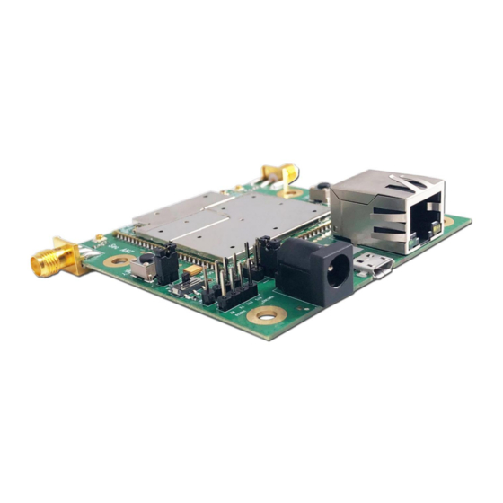
- Page 1 User Manual of FDM-6600 2*2 MIMO Wireless Point to Multi-Point Ethernet & Full Duplex TTL Serial Data Board 1 / 16 www.iwavecomms.com...
-
Page 2: Table Of Contents
Catalogue 1.Hardware ................................. 3 1.1. Interface ............................... 3 1.1.1.COMUART ...........................3 1.1.2. RJ45 Port ............................6 2. Software ................................7 2.1. WebUI Login ............................7 2.2.Home Page Debugging Switch ......................8 2.3.Key Setting .............................9 2.4.Master-slave Setting ..........................9 2.5. Wireless Setting ............................9 2.6.Network Parameter Setting ........................ -
Page 3: Hardware
Transmission Mode: Pass-through mode The data transmitting and receiving is broadcast in the network. After successful networking, each FDM-6600 node can receive serial data. Note: If you want to distinguish between sending, receiving and control, you need to define the... - Page 4 Baud rate 115200 = 115200 (bits/sec) = 10.27 (KB/sec) How to test if the COMUART works normally? Item Computer (with software sscom42 or other serial software such as putty, Serial Port Tester, CommMonitor3.0, Serial Interface, etc.) FDM-6600 Antenna TTL-USB Cable Power Adapter(5V/2A) TTL-USB Module 4 / 16...
- Page 5 FDM-6600 USB Module Connect FDM-6600 with Computer Conenct the antennas with FDM-6600 Power the board using the adapter we supplied(DC5V/2A) Connect the board with your computure by TTL-USB Cable. After the driver is installed correctly, the computer will display the following COM port...
-
Page 6: Rj45 Port
Sending and Receiving Serial data through the COMUART Computer Settings: Then you can send and receive serial data via both FDM-6600 COMUART 1.1.2. RJ45 Port Item Computer IP Camera FDM-6600 Antenna RJ45 Cable Power Adapter(5V/2A) Connect FDM-6600 with Computer and Camera 1. -
Page 7: Software
8. Enter into IP Camera's user name and password, then you will get the IP Camera's video on the computer. How to use NVR to get the camera's video Connect IP Camera with FDM-6600 as to below settings: Subnet Mask Gateway 170.18.15.6... -
Page 8: Home Page Debugging Switch
User name: admin123 Password: admin123 Administrator login user name and password(password and user name changing is not supported) Administrator username: admin123 Administrator password: admin123 After registering and changing the password, it will automatically log in and jump to the index page. -
Page 9: Key Setting
2.3.Key Setting Before networking, each node need to enter into the key 2.4.Master-slave Setting In the same network, only one central node is allowed, and the others are all access nodes. 2.5. Wireless Setting Set the frequency band Frequency Hopping Management 9 / 16 www.iwavecomms.com... -
Page 10: Network Parameter Setting
Bandwidth Building Chain Management: Input the frequency point and bandwidth. 2.6.Network Parameter Setting Set IP address of the node. The initial IP address is http://192.168.1.12 10 / 16 www.iwavecomms.com... -
Page 11: Uplink And Downlink Setting
2.7.Uplink and Downlink Setting Four uplink and downlink modes: config0(2D3U) config1(3D2U) config2(4D1U) config3(1D4U) D=DOWN, U=UP Note: Only the central node can modify the uplink and downlink settings, and the device needs to be restarted to take effect after the setting is successful. ... -
Page 12: Vcom
17.80254 11.61035 5.805176 24.38174 10.83633 17.02852 23.60772 5.418164 27.47871 17.9209 8.96045 37.63389 16.72617 26.28398 36.43916 8.363086 2.8.VCOM 2.9.Debug Interface Actively report information such as IP address, signal strength, RSRP, etc. DRPR Report 12 / 16 www.iwavecomms.com... -
Page 13: Device Information
Shell debugging interface, which can execute the shell commands. AT debug interface 2.10.Device Information Show the version information of the device 13 / 16 www.iwavecomms.com... -
Page 14: At Commands Supported By Webui
3. AT Commands Supported by WebUI 3.1.Command Set Supported by AT Debug Interface WebUI supports the following AP side AT commands "AT+CFUN" "AT^LCMFUN" "AT^DTSET" "AT^NETIFCFG" "AT^DGMR" "AT^DFGMR" "AT^RCVR" "AT^DAMR" "AT^POWERCTL" "AT^CAMERATL" "AT^RMTCTL" "AT^ELFUN" "AT^ELCH" "AT^ELCFGUL" "AT^RECOVSET" "AT^APLFUN" "AT^VCOMFUN" "AT^DHCPSET" "AT^DHDRSET" 3.2.Explanation of AT Command in WebUI Explanation of AT Command in WebUI Menu... - Page 15 Debug Success or at+cfun= 0 or 1 Single Selection Switch Failure at+cfun=0 at^dapi="X" Must be hexadecimal, i.e. 0~9, A~F at+cfun=1 or A~F, and must not exceed 64 ch It can only be s Rule: For commands that ca "must be even num Success or aracters, i.e.
- Page 16 m version number ion number Query the physical laye Displays the physical layer versi AT^DCMR=17 r version number on number Query the high-level v Displays the high-level version AT^DCMR=18 ersion number number Single Selection Success or failure VCOM at^vcomfun=X 0 or 1 1: vcom open prompt to power off and rest 0: vcom close...
Need help?
Do you have a question about the FDM-6600 and is the answer not in the manual?
Questions and answers