
Related Manuals for iWave FDM-615PTM


Summary of Contents for iWave FDM-615PTM
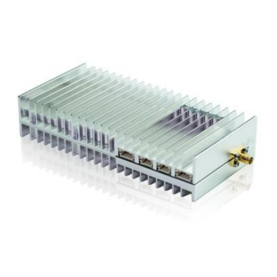
- Page 1 User Manual of FDM-615PTM 100km-150km 2*2 MIMO and PtMP Drone HD Video Downlink 1 / 15 www.iwavecomms.com...
-
Page 2: Table Of Contents
Catalogue 1. Hardware ......................................3 1.1. Interface ....................................3 1.2. Indicator ....................................3 1.3. Notice ....................................4 2. Software ......................................4 2.1. WebUI Operation ..................................4 2.1.1. Home Page Debugging Switch..........................5 2.1.2.Key Setting ................................6 2.1.3.Master-slave Setting ...............................6 2.1.4. Wireless Setting ..............................6 2.1.5.Network Parameter Setting ..........................8... -
Page 3: Hardware
1. Hardware 1.1. Interface 1.2. Indicator 3 / 15 www.iwavecomms.com... -
Page 4: Notice
Central-Access Indicator: The indicator will be bright (central node). The indicator will blink (Access node). Ethernet Indicator After power on, it will be fast blink for self-check. When it works normally, it will blink according to the data stream. Signal Strength Indicator The color of the indicator Green→Yellow→Red→Off The change in color from green to red indicates that the signal strength goes from strong to weak. -
Page 5: Home Page Debugging Switch
overwritten. After the factory settings are restored, the account and password are restored to their initial values. "Login", "Registration", "Modify Password" need to configure the IE browser, tools-options-Internet options-security settings-enable ActiveX controls and plug-ins. Note: Administrator login does not require the above steps. ... -
Page 6: Key Setting
2.1.2.Key Setting Before networking, each node need to enter into the key 2.1.3.Master-slave Setting In the same network, only one central node is allowed, and the others are all access nodes. 2.1.4. Wireless Setting Set the frequency band 6 / 15 www.iwavecomms.com... - Page 7 Frequency Hopping Management Bandwidth Building Chain Management: Input the frequency point and bandwidth. 7 / 15 www.iwavecomms.com...
-
Page 8: Network Parameter Setting
2.1.5.Network Parameter Setting Set IP address of the node. The initial IP address is http://192.168.1.XX 2.1.6.Uplink and Downlink Setting Four uplink and downlink modes: config0(2D3U) config1(3D2U) config2(4D1U) config3(1D4U) D=DOWN, U=UP Note: Only the central node can modify the uplink and downlink settings, and the device needs to be restarted to take effect after the setting is successful. -
Page 9: Vcom
the actual downlink bandwidth is as follows(The data is laboratory test data) Data Rate(Mbps) Bandwith(MHz) 1.675586 1.092773 0.546386 2.294824 0.752198 1.385009 2.053467 0.236768 4.775196 3.114257 1.557129 6.539941 2.70205 4.487988 6.385547 1.45332 8.571094 5.589844 2.794922 11.73867 4.85376 7.94751 11.23462 2.608594 17.80254 11.61035 5.805176 24.38174... - Page 10 DRPR Report Shell debugging interface, which can execute the shell commands. AT debug interface 10 / 15 www.iwavecomms.com...
-
Page 11: Device Information
2.1.9.Device Information Show the version information of the device 3.AT Commands Supported by WebUI 3.1.Command Set Supported by AT Debug Interface WebUI supports the following AP side AT commands "AT+CFUN" "AT^LCMFUN" "AT^DTSET" "AT^NETIFCFG" "AT^DGMR" "AT^DFGMR" "AT^RCVR" "AT^DAMR" "AT^POWERCTL" 11 / 15 www.iwavecomms.com... -
Page 12: Explanation Of At Command In Webui
"AT^CAMERATL" "AT^RMTCTL" "AT^ELFUN" "AT^ELCH" "AT^ELCFGUL" "AT^RECOVSET" "AT^APLFUN" "AT^VCOMFUN" "AT^DHCPSET" "AT^DHDRSET" 3.2.Explanation of AT Command in WebUI Explanation of AT Command in WebUI Menu Commands X Value Remark Prompt Debug Success or at+cfun= 0 or 1 Single Selection Switch Failure at+cfun=0 at^dapi="X"... - Page 13 IP addres Comply with IP addr X is a space to manually enter any Success or at^netifcfg=2,"X.X.X.X" s Setting ess regulations number Failure Bandwidt Success or at^drps=,X, 0 or 1 or 2 or 3 or 5 Single Selection Local settings Failure settings Bandwidt...
-
Page 14: Case
4.Case 4.1.Configuration Power on the FDM-615PTM and connect it with PC. Default IP Address: Center node:192.168.1.3/24 Access node:192.168.1.2/24 Access node:192.168.1.4/24 Set the computer IP wtih same network segment address. Such as 192.168.1.99/255.255.255.0 Visit device default IP via IE browser(version 11) and input the user name and password. Then you can configure the device per your requirement. - Page 15 FDM-615PTM. Notice: FDM-615PTM defaults 2-layer routing and forwarding. If there is no IP conflicts, you can use the default gateway and IP. If you want to change the gateway and IP, please update the IP on WebUI, and then restart it.
Need help?
Do you have a question about the FDM-615PTM and is the answer not in the manual?
Questions and answers