
Related Manuals for iWave FD-6100


Summary of Contents for iWave FD-6100
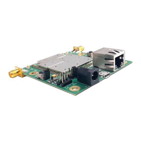
- Page 1 User Manual of FD-6100 2*2 MIMO Wireless MESH Ethernet & Full Duplex TTL Serial Data Board 1 / 16 www.iwavecomms.com...
-
Page 2: Table Of Contents
Catalogue 1. Hardware ............................3 1.1. Interface ..........................3 1.1.1.COMUART ........................3 1.1.2. RJ45 Port ........................6 2. Software ............................8 2.1. WebUI Login ...........................8 2.1.1. Home Page Debugging Switch ..................9 2.1.2. Key Setting ........................9 2.1.4. Wireless Setting ......................10 .................. -
Page 3: Hardware
1. Hardware 1.1. Interface Note: Using a 5V/2A adapter for power supply. Before powering on, set the two DIP switches to the left side. Please install the antennas firstly before powering on. Or the device will be burn out. ... - Page 4 The data transmitting and receiving is broadcast in the network. After successful networking, each FD-6100 node can receive serial data. Note: If you want to distinguish between sending, receiving and control, you need to define the format yourself Baud Rate: The max baud rate is 115200bps(The total rate of unidirectional receiving or...
- Page 5 Connect TTL-USB cable with FD-6100 FD-6100 USB Module Connect FD-6100 with Computer Connect the antennas with FD-6100 Power the board using the adapter we supplied(DC5V/2A) Connect the board with your computer by TTL-USB Cable. 5 / 16...
-
Page 6: Rj45 Port
After the driver is installed correctly, the computer will display the following COM port information Sending and Receiving Serial data through the COMUART Computer Settings: Then you can send and receive serial data via both FD-6100 COMUART 1.1.2. RJ45 Port Item Computer 6 / 16 www.iwavecomms.com... - Page 7 8. Enter into IP Camera's user name and password, then you will get the IP Camera's video on the computer. How to use NVR to get the camera's video Connect IP Camera with FD-6100 as to below settings: 7 / 16 www.iwavecomms.com...
-
Page 8: Software
255.0.0.0 170.18.15.1 Note: Since NVR can automatically send ARP packets, so it can be set with different subnet network with FD-6100 2. Software 2.1. WebUI Login WebUI interface operation is mainly to manually select the corresponding parameters or input relevant parameters, configure the nodes, and return the configuration status displayed on the UI interface. -
Page 9: Home Page Debugging Switch
2.2.Home Page Debugging Switch Modem switch setting: open/close Modem Restart Setting 2.3.Key Setting Before networking, each node need to enter into the key 2.4.Master-slave Setting Select the AUTO and no need to modify it. 9 / 16 www.iwavecomms.com... -
Page 10: Wireless Setting
2.5. Wireless Setting Set the frequency band Frequency Hopping Management Bandwidth 10 / 16 www.iwavecomms.com... -
Page 11: Network Parameter Setting
Building Chain Management: Input the frequency point and bandwidth. 2.6.Network Parameter Setting Set IP address of the node. The initial IP address is http://192.168.1.12 2.7.Uplink and Downlink Setting Four uplink and downlink modes: config0(2D3U) config1(3D2U) config2(4D1U) config3(1D4U) 11 / 16 www.iwavecomms.com... -
Page 12: Vcom
D=DOWN, U=UP Note: Only the central node can modify the uplink and downlink settings, and the device needs to be restarted to take effect after the setting is successful. There is no need to manually change the access node’s configuration. Becasue the access node will automatically change its configuration according to the central node and obtain the new configuration after it access to the network. -
Page 13: Debug Interface
2.9.Debug Interface Actively report information such as IP address, signal strength, RSRP, etc. DRPR Report Shell debugging interface, which can execute the shell commands. AT debug interface 13 / 16 www.iwavecomms.com... -
Page 14: Device Information
2.10.Device Information Show the version information of the device 3. AT Commands Supported by WebUI 3.1.Command Set Supported by AT Debug Interface WebUI supports the following AP side AT commands "AT+CFUN" "AT^LCMFUN" "AT^DTSET" "AT^NETIFCFG" "AT^DGMR" "AT^DFGMR" "AT^RCVR" "AT^DAMR" "AT^POWERCTL" 14 / 16 www.iwavecomms.com... -
Page 15: Explanation Of At Command In Webui
"AT^CAMERATL" "AT^RMTCTL" "AT^ELFUN" "AT^ELCH" "AT^ELCFGUL" "AT^RECOVSET" "AT^APLFUN" "AT^VCOMFUN" "AT^DHCPSET" "AT^DHDRSET" 3.2.Explanation of AT Command in WebUI Explanation of AT Command in WebUI Menu Commands X Value Remark Prompt Debug Success or at+cfun= 0 or 1 Single Selection Switch Failure at+cfun=0 at^dapi="X"... - Page 16 Bandwidth Success or at^drps=,X, 0 or 1 or 2 or 3 or 5 Single Selection Local settings settings Failure Bandwidth Chain group se Success or at^drpc=,X, 0 or 1 or 2 or 3 or 5 Single Selection settings ttings Failure Power Chain group se Success or...
Need help?
Do you have a question about the FD-6100 and is the answer not in the manual?
Questions and answers