Advertisement
Quick Links
Contents
I. Disclaimer ................................................................................................................................................................ 2nd
II. Precautions for integration .................................................................................................................................... 2nd
III. List of in-box items ................................................................................................................................................. 4th
IV. Interface Definition ................................................................................................................................................ 4th
VI. Antenna Installation .............................................................................................................................................10th
6.1. Multi-rotor UAV ..........................................................................................................................................10th
6.2. Fixed Wing UAV ..........................................................................................................................................11th
www.iwavecomms.com
FIM-2405 User Manual
RX on Ground & TX on Board
IWAVE COMMUNICATIONS CO., LIMITED
V2.0
1st
Advertisement

Subscribe to Our Youtube Channel
Related Manuals for iWave FIM-2405


Summary of Contents for iWave FIM-2405
-
Page 1: Table Of Contents
FIM-2405 User Manual RX on Ground & TX on Board Contents I. Disclaimer ................................2nd II. Precautions for integration ............................ 2nd III. List of in-box items ..............................4th IV. Interface Definition ..............................4th V. Operating Instructions & Steps ..........................7th VI. -
Page 2: Disclaimer
COMMUNICATIONS CO., LIMITED reserves all copyrights of the product and the manual. All the information must not be copied or reproduced in any form without permission of IWAVE. There may be semantic differences between disclaimers of different languages. The Chinese version shall prevail in Chinese mainland, while the English version shall prevail in other regions. - Page 3 10) Before using, please make sure all cables are in good connection and all components can work properly. 11) After starting the product, the self-test indicators of FIM-2405 will continuously blink for 30s and then keep bright. Tx camera’s video shown on the monitor connected with Rx means the device works properly.
-
Page 4: List Of In-Box Items
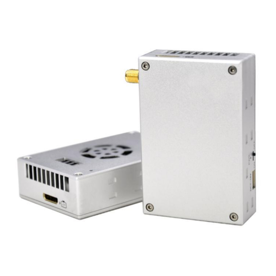
3. List of in-box items On board x1 Ground terminal x1 On board antenna x1 Ground antenna x1 Power cable x4 HDMI video cable x2 Network cable x4 S2 Cable: TTL Serial port cable x3(use for S2 port) Serial TTL to USB serial port x4(use for S1 port) SMA Cable(Copper wire tinned shield semi-soft line) x4 Interface Definition... - Page 5 A: HDMI Port on Rx B: SMA Port C: HDMI Port on Tx D: Working Status Indicator E: S1 TTL Serial Port F: DC7~18V Input G: Power On/Off H: S2 TTL Serial Port I: Ethernet Port J: WAN LED K: LAN LED L: Mounting Hole Note: S1 and S2 is same function.
- Page 6 Light 1,2,3 on: Signal Strong (2) lights of 1, 2, and 3 are flashing repeatedly in sequence which means the device pairing is unsuccessful, and Rx and Tx do not communicate. (3) No. 4 is a data communicate indicator. When data is transmitting normally, No.4 light will keep red. Or it will not light.
-
Page 7: Operating Instructions & Steps
Serial Cable for S2 ZH No. Color Signal Yellow White Black 6.Operating Instructions & Steps 5.1. Make TX and RX and accessories ready. Besides the items we supply in package box: Tx, Rx, Antennas, Power Cables, Antenna Cable, Ethernet Cable, Serial Cable and HDMI Cable, you also need to prepare monitor, battery, camera and PC. - Page 8 5.2.Connection Make the power cable, HDMI Cable, Ethernet cable, serial port cable and antenna in good connection. www.iwavecomms.com...
- Page 9 5.3. Power on After checking all the connections are in good condition, turn on the the video source, LCD display, transmitter and receiver. The PWR indicator will bright and the whole system starts to work. 5.4. Observe the each indicator’s status When the device begin to normally start work, all indicators status is described as follow: After power on, light 1,2,3 turn green, light 6 turns blue.
-
Page 10: Antenna Installation
6. Antenna Installation 6.1. Multi-rotor UAV SMA Feeder Cable 1) Using SMA metal shielded semi-flexible blue feeder cable provided by IWAVE to connect the TX SMA port with antenna. 2) The antenna needs to be mounted vertically downwards. 3) The best installation location is UAV ground bracket. With antenna inside, the bracket can only use fiberglass material. -
Page 11: Fixed Wing Uav
6.2. Fixed Wing UAV 1) Using SMA metal shielded semi-flexible blue feeder cable provided by IWAVE to connect the TX SMA port with antenna. 2) The antenna needs to be mounted vertically downwards. 3) The best installation position is center of UAV tail, prominent outside the body and vertical downward. - Page 12 The second optional mounting position is located below the wing and body joints, vertical down, as far as possible away from the wing but near the machine abdomen, protruding below the abdomen level. www.iwavecomms.com 12th...
Need help?
Do you have a question about the FIM-2405 and is the answer not in the manual?
Questions and answers