Table of Contents
Advertisement
Quick Links
TX
Contents
I. Disclaimer ................................................................................................................................................................ 2nd
II. Precautions for integration .................................................................................................................................... 2nd
III. List of in-box items ................................................................................................................................................. 4th
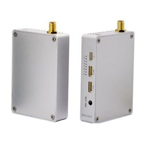
IV. Interface Definition ................................................................................................................................................ 4th
4.1. RF Interface .................................................................................................................................................. 4th
4.2. Ethernet Port ................................................................................................................................................5th
4.3. Power Input Interface .................................................................................................................................. 5th
4.4. Serial Port: : H 1.0mm 5P .............................................................................................................................5th
5.1. Make TX and RX and accessories ready. ...................................................................................................... 5th
5.2. Connection ................................................................................................................................................... 6th
5.3. Power on ...................................................................................................................................................... 6th
5.4. Definition of indicators ................................................................................................................................ 6th
5.5. Start completed ............................................................................................................................................7th
VI. Antenna Installation ...............................................................................................................................................7th
6.1. Multi-rotor UAV ............................................................................................................................................7th
6.2. Fixed Wing UAV ............................................................................................................................................8th
VII. Software Operation .............................................................................................................................................. 8th
www.iwavecomms.com
FIP-2405 User Manual
RX
1st
Advertisement
Table of Contents

Related Manuals for iWave FIP-2405


Summary of Contents for iWave FIP-2405
-
Page 1: Table Of Contents
FIP-2405 User Manual Contents I. Disclaimer ................................2nd II. Precautions for integration ............................ 2nd III. List of in-box items ..............................4th IV. Interface Definition ..............................4th 4.1. RF Interface ..............................4th 4.2. Ethernet Port ..............................5th 4.3. Power Input Interface ..........................5th 4.4. -
Page 2: Disclaimer
COMMUNICATIONS CO., LIMITED reserves all copyrights of the product and the manual. All the information must not be copied or reproduced in any form without permission of IWAVE. There may be semantic differences between disclaimers of different languages. The Chinese version shall prevail in Chinese mainland, while the English version shall prevail in other regions. - Page 3 11) Adjust the Futaba controller into French mode as following steps: [LINKAGE MENU]→FRQUENCY→ RTN b→ [AREA]→[FRANCE] Or connect FIP-2405 S1 serial port with trainer interface on back side of Futaba by TTL cable. And set the Futaba RF as OFF. Through the S1 port uplink the PPM/SBUS signal.
-
Page 4: List Of In-Box Items
III. List of in-box items On board x1 Ground terminal x1 On board antenna x1 Ground antenna x1 DC to DC power cable x2 Network cable x4 Serial port cable x1 (Length: 20cm) Serial port cable x1 (Length: 1500cm) USB cable of serial port 2 x1 SMA Cable(Copper wire tinned shield semi-soft line) x1 IV. -
Page 5: Ethernet Port
4.2. Ethernet Port ETH: EZH 4P 1.5mm ETH Signal Definition 4.3. Power Input Interface DC: 3.5×1.35(Male) to 5.5×2.1(Female) 4.4. Serial Port: : H 1.0mm 5P SH 5P NO. Definition 3.3V No Definition V. Operating Instructions & Steps 5.1. Make TX and RX and accessories ready. Besides the whole equipment we supply, you also need to make sure the IP Camera, display and power ready before operating. -
Page 6: Connection
5.2. Connection Make the power cable, Ethernet cable, serial port cable and antenna in good connection. (the serial port cable is for data links) 5.3. Power on After checking all the connections are in good condition, turn on the the video source, LCD display, transmitter and receiver. -
Page 7: Start Completed
UAV. About how to install the antenna on UAV please refer the following description. VI. Antenna Installation 6.1. Multi-rotor UAV SMA Feeder Cable 1) Using SMA metal shielded semi-flexible blue feeder cable provided by IWAVE to connect the TX SMA port with antenna. 2) The antenna needs to be mounted vertically downwards. -
Page 8: Fixed Wing Uav
6.2. Fixed Wing UAV 1) Using SMA metal shielded semi-flexible blue feeder cable provided by IWAVE to connect the TX SMA port with antenna. 2) The antenna needs to be mounted vertically downwards. 3) The best installation position is center of UAV tail, prominent outside the body and vertical downward. - Page 9 change one of them, you have to change another one, or they will lose connection. There are two ways to modify the parameters. 1) Connect Transmitter or Receiver to PC one by one then change the parameters. STEP 1 STEP 2 2) when Tx and Rx are working and the communication between them is successful, you can remotely change one’s parameters which is not connected to the PC through another one which is connected to PC.
- Page 10 3) Enter the IP address(Tx IP: 192.168.11.1 ; Rx IP: 192.168.11.2),Next click Connect TDD button. If you want to Restart OFDM software, click Restart-TDD button www.iwavecomms.com 10th...
- Page 11 2. RF Configuration Method In this section, you can modify six parameters. 2.1. TX Rate(Default: QPSK FEC 1/2) This setting determines the modulation type and in turn the rate at which the data is to be wirelessly transferred. For example: QPSK FEC 1/2: when the bandwidth is 4Mhz, the bit rate that allowed to pass by is half of the bandwidth, namely 2Mhz.
- Page 12 However, the bigger bit rate, the shorter distance. The same to bandwidth. Setting to the highest rate with a poor link may result in reduced performance. 2.2.Channel-Frequency(Default:2479Mhz) You can choose from 2402 to 2482. 2.3. Wireless Distance(Default: 5000m) The Wireless Distance parameter allows a user to set the expected distance the wireless signal needs to travel.
- Page 13 3.2 Data Format(Default: 8N1) This setting determines the format of the data on the serial port.The default is 8 data bits, No parity, and 1 Stop bit. 4.RS2 Configuration method This setting determines which protocol the serial server will use to transmit serial port data over the OFDM network.
- Page 14 Default: 256 Notes: If you want to change parameters here, for example UDP IP , not only you have to write a new address into the first blank, but also should tap into all the following three parameters into the blanks, then click the button Serial UDP mode .
- Page 15 6.3 INIT CONFIG Initialization setting . TX for transmitter initialization, and RX for receiver initialization. We suggest that when you initialize one device, initialize aonther one at the same time. www.iwavecomms.com 15th...
Need help?
Do you have a question about the FIP-2405 and is the answer not in the manual?
Questions and answers