Advertisement
Quick Links
FIP-2420 User Manual
To Costumers
Thank you very much for your favor of our products! This manual describes the usage of the
FIP-2420 and amis to enable you quickly grasp the use of the product.
Copyright Information
This document is copyright-protected by IWAVE COMMUNICATIONS co., ltd. Laws in China and/or other
countries or areas protect the exclusive rights of the Company. The Company endeavors to achieve the
accuracy and completeness of this manual, but no warranty of accuracy or reliability is given. All the
specifications and designs are subject to change without notice due to continuous technological
development. No part of this manual may be copied, modified, translated, or distributed in any manner
without the prior written consent of the Company.
If you have any suggestions or would like to receive more information, please visit our website at:
http://www.iwavecomms.com, or email us support@iwavecomms.com.
www.iwavecomms.com
3F, 19th Bldg, No.1515 Gumei Road, Minhang District, Shanghai, China
Version 2.0.1(4)
Date 6/24/2018
IWAVE COMMUNICATIONS Co.,Ltd
添 加 标 题
1
Advertisement

Related Manuals for iWave FIP-2420


Summary of Contents for iWave FIP-2420
- Page 1 FIP-2420 User Manual To Costumers Thank you very much for your favor of our products! This manual describes the usage of the FIP-2420 and amis to enable you quickly grasp the use of the product. Version 2.0.1(4) Date 6/24/2018 IWAVE COMMUNICATIONS Co.,Ltd 3F, 19th Bldg, No.1515 Gumei Road, Minhang District, Shanghai, China...
-
Page 2: Table Of Contents
FIP-2420 User Manual Contents 1. Introduction........................... 2. Package List........................... 3. Precautions....................4 4. Interfaces and Indicators ....................5 5. Operating Instructions & Steps....................7 Antenna Installation......................8 7. Software Operation..........................10... -
Page 3: Introduction
FIP-2420 User Manual 1. Introduction FIP-2420 is 2.4Ghz point-to-point drone digital Ethernet data downlink radio for 18km-22km range. It supports two way TCPIP/UDP Ethernet data and duplex serial data transmission. 2.Package List... -
Page 4: Precautions
8. Check the surrounding environment to ensure there is no other 2.4GHz devices or they will cause interference with FIP-2420. 9. After powering on FIP-2420, the self-test indicator will continuously blink for 30s and then keep bright. After the camera's video shown on the display, which means the Tx and Rx work properly now. -
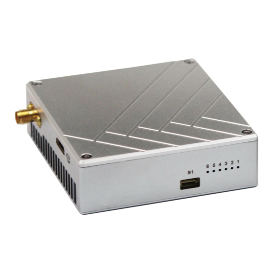
Page 5: Interfaces And Indicators
FIP-2420 User Manual 4. Interfaces and Indicators 4.1. Interfaces Power Input Interface and Power Cable Power Input: Pull - type switch Power Connector: XT30PW-F(Female) Power Cable: One end XT30PW(Male), the other end DC(female) S1 Serial Port: 5P GH with lock socket(GH 1.25mm, we only use 4P) - Page 6 FIP-2420 User Manual RS232 Interface RS232: 3p GH with lock socket(GH 1.25mm) GH 3P Signal Definition RXD RF Interface RF: Standard SMA to connect with antenna or feeder cable ETH: EZH 4P 1.5mm Ethernet Signal Definition...
-
Page 7: Operating Instructions & Steps
FIP-2420 User Manual 5. Operating Instructions & Steps 5.1. Connection Make the power cable, Ethernet cable, serial cable and antenna are in good connection. The serial port(S1) and RS232 on Tx are used to connect with the fly control system such as Pixhawk or gimbal control Note: RS232 and S1 can not be used simultaneously. -
Page 8: Antenna Installation
FIP-2420 User Manual 6. Antenna Installation 6.1. Multi-rotor UAV 1)Using SMA cable provided by IFLY to connect the TX SMA port with antenna. 2)The antenna needs to be mounted vertically downwards. 3)The best installation location is UAV ground bracket and the bracket need to be fiberglass material. - Page 9 FIP-2420 User Manual 6.1. Fixed Wing or VTOL Drone 1. The best installation position is center of UAV tail, prominent outside the body and vertical downward. 2. The second optional mounting position is located below the wing and body joints, vertical down, as far as...
-
Page 10: Software Operation
FIP-2420 User Manual 7. Software Operation Note: Because Tx and Rx are working in pairs, so their parameters need be consistent, which means when one unit parameters are changed, the other unit parameters need to be change too. Or they will lose connection. - Page 11 FIP-2420 User Manual 7.1. Start The Software 1)Right-click the icon to choose“Run as administer” 2)Enter the IP address(Tx IP: 192.168.11.1 ; Rx IP: 192.168.11.2), Next click ConnectTDD button RESETTDD If you want to Restart OFDM software, click button. Notice: You must restart the software after finishing modifying TX or RX parameters. Then type in another one’s IP address, connect and modify its parameters.
- Page 12 FIP-2420 User Manual 7.2. RF Configuration In this section, you can modify six parameters. TX Rate(Default: QPSK FEC 1/2) This setting determines the modulation type and the rate at which the data is wirelessly transferred. For example: Auto: The data will be transmitted at the highest possible rate in consideration of the receive signal...
- Page 13 FIP-2420 User Manual Channel Bandwidth(Default: 4Mhz) The bandwidth channel can be selected from the list. Note: Before choosing the bandwidth please refer to the specifications to see the relationship and performance between channel bandwidth , throughput and sensitivity. Generally a larger channel has greater throughput at the cost of sensitivity, while a smaller channel tends to be more robust, but at the cost of throughput.
- Page 14 FIP-2420 User Manual RX TX Mode TX Master - A Master provide a wireless data connection to slave. RX Slave- A Salve sustain one wireless connection to Master. TX Power(Default: 33dBm) This setting establishes the transmit power level which will be presented to the antenna connector of the TDD_COFDM.
- Page 15 FIP-2420 User Manual Data Baud Rate(Default: 115200) The serial baud rate is the rate at which the modem is to communicate with the attached local asynchronous device. Data Format(Default: 8N1) This setting determines the format of the data on the serial port.The default is 8 data bits, No parity, and 1 Stop bit.
- Page 16 FIP-2420 User Manual 7.5. IP New Network Configuration This setting helps you to change the IP address of devices. The master default IP 192.168.55.1 the slave default IP 192.168.55.2 For example,you want to change the master's IP address to “192.168.55.5”. Then do as the following steps.
- Page 17 FIP-2420 User Manual INIT CONFIG TX means transmitter initialization and RX means receiver initialization. We suggest that when you initialize one device, please initialize another one at the same time. Connect last IP For quickly connect to last IP...
Need help?
Do you have a question about the FIP-2420 and is the answer not in the manual?
Questions and answers