Table of Contents
Advertisement
Quick Links
Advertisement
Table of Contents

Related Manuals for iWave FIM-2450


Summary of Contents for iWave FIM-2450
- Page 1 FIM-2450 User Manual July 2019 Version 1.0...
- Page 2 Document Revisions Version Date Document Changes Number July 2019 Initial Version...
-
Page 3: Table Of Contents
Table of Contents Introduction ............................4 Connectors and LEDs ........................5 Setting up FIM-2450 units ........................ 9 3.1 ... Default Network Configurations .......................9 3.2 ... Setting up steps ..........................9 Details and Notice .......................... 11 4.1 ... Ethernet Cable ..........................11 4.2 ... -
Page 4: Introduction
1 Introduction FIM-2450 is the model name of middle-to-long range (20~30km) point-to-point video transmission devices. Each set of FIM-2450 contains the following it FIM-2450s One transmitter unit, with a camera logo on it One receiver unit, with a monitor logo on it ... -
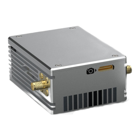
Page 5: Connectors And Leds
Each kind of cable/componet is packed in its own transparent bag labeled with model name. The itFIM-2450s may subject to change due to different customer specific configurations Please refer “FIM-2450 technical specification” for specifications and parameters Connectors and LEDs Front Side of Transmitter Front Side of Receiver ... - Page 6 One 4P LAN connector to connect the 4P header of the Ethernet cable. The LAN port is for configuring FIM-2450 with TDD_COFDM software, also can be used to transmit data (the total throughput of video/LAN/serial data should be less than the max...
- Page 7 One 6P Serial connector, to connect RS232-Serial cable. The voltage is +-13V. There are two serial ports in this connector. FIM-2450 transmits serial data transparently over the wireless connection. Six LEDs One SMA connector, to connect an antenna. Both left side and right side SMA ...
- Page 8 One power connector, to connector a power cable, the voltage range is 10~18V, Don’t input power higher than 18V, otherwise the unit might be damaged. No warranty for over voltage damage. Bottom Side An air intake is on this side, and the cooling-fan is right below the intake. After power on, ...
-
Page 9: Setting Up Fim-2450 Units
3 Setting up FIM-2450 units 3.1 Default Network Configurations FIM-2450 units are working as WiFi bridges, the transmitter and receiver bridge devices connected to thFIM-2450 and forward ethernet frames transparently. Default IP Address of FIM-2450 units Transmitter Receiver 192.168.55.1 192.168.55.2... - Page 10 After both units found other side and established wireless connection successfully, LED 2,3,4 will stop flashing by order, and will be showing the wireless signal strength according by following table LED2 LED3 LED4 Signal Strength Index Flashing Flashing Flashing by 2342….. order No connection ...
-
Page 11: Details And Notice
4 Details and Notice 4.1 Ethernet Cable One header is standard RJ45 Another header is 4P Molex 53261 header (note: Wire color is irrelevant) Pin number Fast Ethernet Signal 4.2 RS232 Serial Cable TTL Serial cable is for transmitting +-13V RS232 Serial signals One header is 6P Molex 53261 header, the pin number shown in following picture, it shows the header side with metal exposed www.iwavecomms.com... - Page 12 Pin number on 53261 header Signal 5V (No connected on this cable) RXD2 TXD2 RXD1 TXD1 Another header consists of 6 Dupont plugs with different color wire: www.iwavecomms.com...
- Page 13 Color of the Dupont plug wire Signal Pure Black (there are 2 pure black wires) Black with a short gray casing RXD2 White TXD2 Yellow RXD1 TXD1 Serial data format Table Default Baud Rate 115200 Data Bits Parity Stop bit Voltage 3.3V www.iwavecomms.com...
-
Page 14: Notice
Don’t input power that voltage is higher than 18V Don’t block the air intake and outlet when the unit is power-on Don’t dismantle or modify FIM-2450 units www.iwavecomms.com...
Need help?
Do you have a question about the FIM-2450 and is the answer not in the manual?
Questions and answers