Table of Contents
Advertisement
Quick Links
FIP-2410 User Manual
Contents
1. Package List .............................................................................................................................................................2nd
2. Precautions .............................................................................................................................................................2nd
3. Interface .................................................................................................................................................................. 4th
4. Installation ...............................................................................................................................................................4th
4.1. Make TX and RX and accessories ready. ...................................................................................................... 5th
4.2. Connection ................................................................................................................................................... 5th
4.3. Power on ...................................................................................................................................................... 5th
5. Software Configuration ........................................................................................................................................... 6th
5.1. Start The Software ....................................................................................................................................... 7th
5.2. RF Configuration ...........................................................................................................................................8th
5.3. RS1 Configuration ...................................................................................................................................... 11th
5.4. RS2 Configuration ...................................................................................................................................... 11th
5.5. IP New Network Configuration .................................................................................................................. 12th
5.6. RF New NET Configuration .........................................................................................................................12th
5.6.4. Connect last IP ........................................................................................................................................ 13th
www.iwavecomms.com
1st
Advertisement
Table of Contents

Related Manuals for iWave FIP-2410


Summary of Contents for iWave FIP-2410
-
Page 1: Table Of Contents
FIP-2410 User Manual Contents 1. Package List ................................2nd 2. Precautions ................................2nd 3. Interface .................................. 4th 4. Installation ................................4th 4.1. Make TX and RX and accessories ready....................... 5th 4.2. Connection ..............................5th 4.3. Power on ..............................5th 5. Software Configuration ............................6th 5.1. -
Page 2: Package List
4) Antennas on board should be kept away from other radio antennas to avoid electromagnetic noise and interference. Do not disassemble or modify IWAVE FIP-2410. Any problem occur during installation, contact IWAVE or IWAVE local branch office. 6) Keep appropriate distances between different electronic devices during installation to minimize the electromagnetic interference. - Page 3 8) Check the surrounding environment to ensure there is no other 2.4GHz devices to cause interference. 9) After starting the product, the self-test indicators of FIP-2410 will continuously blink for 30s and then keep bright. Only after the video from the camera shown on the display, then you can confirm that the device work properly now.
-
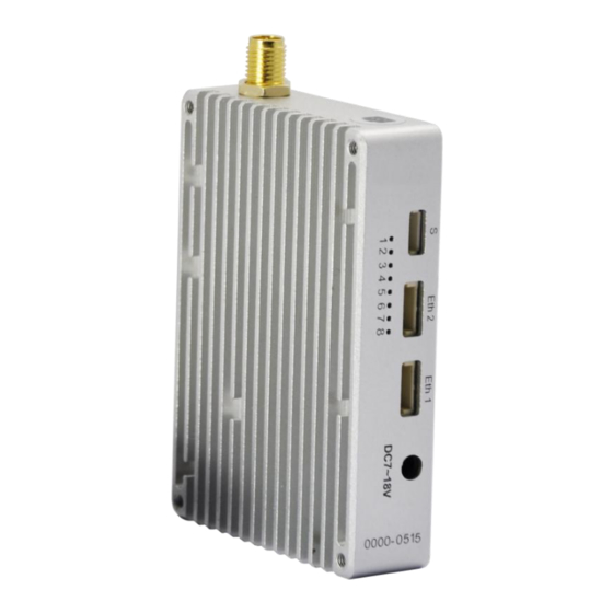
Page 4: Interface
3. Interface Note: signal light meaning is as follows 1) After powering on, light 1,2,3 turn green, light 6 turns blue and light 8 turns red. 2) After 1 second, light 1, 2, 3 and 6 start to blink. Light 5 and 8 will keep constant light. 3) After a few seconds, the starting completed. -
Page 5: Make Tx And Rx And Accessories Ready
4.1. Make TX and RX and accessories ready. Besides the whole equipment we supply, you also need to make sure the IP Camera, display and power source ready before installation. 4.2. Connection Make the power cable, Ethernet cable, serial port cable and antenna in good connection. -
Page 6: Software Configuration
5. Software Configuration User’s Manual of TDD_COFDM V1.5 Note: As our devices are working pairs, so their parameters need be consistent, which mean when www.iwavecomms.com... -
Page 7: Start The Software
one unit parameters are changed, the other unit parameters need to be change too. Or they will lose connection. The following show you two ways to do the parameters settings: (1) Connect Tx or Rx with PC separately then change their parameters one by one. (2) When the communication between Tx and Rx are working normally, you can change the remote unit parameters through the local unit and then change the local unit parameters. -
Page 8: Rf Configuration
Enter the IP address(Tx IP: 192.168.11.1 ; Rx IP: 192.168.11.2),Next click Connect TDD button If you want to Restart OFDM software, click Restart-TDD button Notice: You must restart the software after finishing modifying TX or RX parameters. Then type in another one’s IP address, connect and modify its parameters. - Page 9 Auto: The data will be transmitted at the highest possible rate in consideration of the receive signal strength (RSSI) If setting a fixed TX Rate, it is recommended to retain a fade margin of at least 10dbm for optimum performance. For example, for a link (8MHz channel) with a signal strength of at least –75dBm, a TX rate of 16-QAM 3/4 FEC is recommended.
- Page 10 5.2.4. Wireless Distance(Default: 10km) The Wireless Distance parameter allows a user to set the expected distance that the wireless signal needs to travel. The TDD-COFDM sets various internal timeouts to account for this travel time. Longer distances will require a higher setting, and shorter distances may perform better if the setting is reduced.
-
Page 11: Rs1 Configuration
5.3. RS1 Configuration In this section, you can modify two parameters listed in the following picture. 5.3.1. Data Baud Rate(Default: 115200) The serial baud rate is the rate at which the modem is to communicate with the attached local asynchronous device. 5.3.2. -
Page 12: Ip New Network Configuration
IP address of distant device to which UDP packets are sent when data received at serial port. Default: 192.168.55.2(master) 192.168.55.1(slave) Remote Port UDP port of distant device mentioned above. Default: 20002 Listening Port UDP port which the IP Series listens to (monitors). UDP packets received on this port are forwarded to the unit’s serial port. -
Page 13: Connect Last Ip
Each network of TDD-COFDM modules must have a unique Network ID. This Network ID must be set same in each unit on the network. You can change it according to your needs , but TX and RX must have the same RF NET ID . Chose the box in front of RF NEW ID , and type in the RF NET ID you choose , then click RF new NET button.
Need help?
Do you have a question about the FIP-2410 and is the answer not in the manual?
Questions and answers