
Related Manuals for AMT Datasouth Fastmark M7XPd


Summary of Contents for AMT Datasouth Fastmark M7XPd
- Page 1 Fastmark M7 Thermal Barcode Printer (Direct & Transfer) User’s Guide © September 2016 AMT Datasouth Corp. Document # 121771...
- Page 2 Information in this manual is subject to change without notice and does not represent a commitment on the part of AMT Datasouth Corporation. No part of this manual may be reproduced or transmitted in any form by any means, for any purpose other than the purchaser’s personal use, without the expressed written permission of AMT Datasouth...
-
Page 3: Table Of Contents
Table of Contents User Caution........................5 Packaging ........................6 Unpacking the printer ............................ 6 Removing protective material ........................6 Introduction ........................7 Product ................................7 Model configuration ............................7 Printer Overview ......................8 Front view ..............................8 Interior view ..............................9 Rear view .............................. - Page 4 Table of Contents Diagnostic Tool ......................49 Start Diagnostic Tool ........................... 49 Printer Function ............................50 Setting Ethernet by Diagnostic Utility ......................50 Using USB interface to setup Ethernet interface ..................51 Using RS-232 interface to setup Ethernet interface ................52 Using Ethernet interface to setup Ethernet interface ................
-
Page 5: User Caution
Operational safety User Caution CAUTION ⚫ ⚫ Refer to the product label (back of the Mechanical and electrical repairs printer) and verify your power source should be conducted by qualified exactly meets those requirements. service personnel. ⚫ ⚫ Do not use this product near heat or Unplug this product from the power water. -
Page 6: Packaging
Packaging Unpacking the printer Printer USB Cable Quick Start Guide AC Power Cord CD ROM Removing protective material Open the packing box, remove the printer. Open right cover and remove foam block from printhead assembly. Remove paper between printhead and platen. If any parts are missing, please contact the Customer Service Department of your purchased reseller or distributor. -
Page 7: Introduction
Introduction Product Thank you for purchasing your AMT Datasouth bar code printer. This printer is designed with a die-cast aluminum chassis and print mechanism, metal cover with large clear media view window, which ensures it working in extreme and heavy duty industrial environments and applications. -
Page 8: Printer Overview
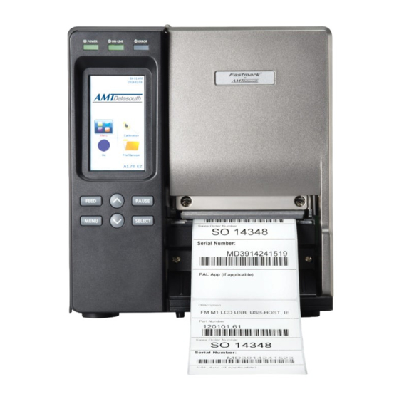
Printer Overview Front view 1. LED indicators 2. Touch screen 3. Front panel buttons 4. Media view window 5. Paper exit chute 6. Printer right side cover - 8 -... -
Page 9: Interior View
Interior view Ribbon rewind spindle Ribbon release button Print head pressure adjustment knobs Z axis mechanism adjustment knob Ribbon tension adjustment knob Print head release lever Media sensor lock knob Ribbon supply spindle Media guide bar & Rear label guide Label roll guard 3”... -
Page 10: Rear View
Rear view Note: 1. External label entrance chute ❖ The above interface picture is for 2. Power cord socket reference only. Please refer to the product specification for the 3. Power switch interfaces availability. 4. Ethernet interface ❖ SD card slot, Ethernet interface and 5. -
Page 11: Operator Controls
Operator Controls Display panel LED’s Touch screen Company Logo Icons Printer firmware version Printer name Keys Indicators Status Indication The printer power is turned off POWER The printer power is turned on Printer is ready ON-LINE Pause Blinking Downloading data into printer Printer is ready ERROR “Carriage Open”... -
Page 12: Key Functions
Key functions Function 1. Enter the menu 2. Exit from a menu or cancel a setting and return to the previous menu Pause/Resume the printing process Advance one label Scroll up the menu list Scroll down the menu list Enter/Select cursor located option Touch Screen Tap a menu Icon to open and use. - Page 13 Scroll down Scroll up - 13 -...
-
Page 14: Installation
Installation Setting up the printer Place the printer on a flat, secure surface. Make sure the power switch is off. Connect the printer to the computer with the provided USB cable. Plug the power cord into the AC power cord socket at the rear of the printer, and then plug the power cord into a properly grounded power outlet. - Page 15 Push the release lever to open the print head mechanism. Install the ribbon onto the supply spindle. Do Not push the release button when installing the ribbon. The release button is only used when removing the ribbon. - 15 -...
- Page 16 Thread the ribbon through the sensor slot, and then through the open space in between printhead and platen. Ribbon Ribbon sensor Wrap the ribbon onto the rewind spindle. Turn the spindle clockwise 3~5 complete turns. Verify the ribbon is properly stretched/flat without wrinkles.
-
Page 17: Removing Used Ribbon
Close the print head mechanism making sure the latches are engaged securely. Ribbon Routing Removing used ribbon Cut ribbon between guide and rewind spindle. - 17 -... - Page 18 Push green button to release ribbon from the spindle. Pull off used ribbon. - 18 -...
-
Page 19: Loading Media Roll
Loading media roll Open the printer right side cover. Push the printhead release lever to open the mechanism. - 19 -... - Page 20 Move the label guard across the spindle and lay it down horizontally. The 3” label spindle can be removed to support a 1” core, by NOTE: removing two screws. Remove Screws Remove 3” spindle - 20 -...
- Page 21 Place the roll of media onto the supply spindle, positioning it to the back of the chassis. Lift and position the label guard against the roll of media. Pull leading edge of label forward over the media guide bar, under the damper, through the media sensor (green) and place the label onto the platen roller.
- Page 22 Unlock the media sensor to adjust. Align sensor (green triangle ) over label gap or black mark for proper sensing. After alignment re-lock sensor. Unlock lock Adjust the label guides to fit the width of the media. ADJUST - 22 -...
- Page 23 Close the print head mechanism and make sure the latches are engaged securely. Media Routing Media calibration is required when changing gap and black mark sensor type. - 23 -...
-
Page 24: Loading Fan Fold Media
Loading fan fold media Open the printer right side cover. Push the printhead release lever to open the mechanism. Insert the fan-fold media through the rear or bottom external label entrance chute. Pull fan-fold label leading edge forward over the media guide bar, under damper, through media sensor and place the media leading edge onto the platen roller. -
Page 25: Loading Media In Peel Mode
Loading media in peel mode Open printer cover. Open print head release lever and pull approximately two feet of label through the front of the printer. Press down on the peel-off release lever to free the roller. Feed the label between peel-off roller and platen roller. Peel off roller - 25 -... - Page 26 Feed label through mechanism. Wrap the label onto the internal rewind spindle and turn the spindle counter-clockwise 3 to 5 turns until the slack is removed and properly stretched. Rewind spindle - 26 -...
- Page 27 Lift up the peel-off roller release lever and close the print head mechanism. Move the peel-off sensor toward the paper exit chute. Close print head mechanism Peel-off Sensor Position Label peeling will automatically start. Press the FEED button to test - 27 -...
-
Page 28: Adjusting Print Head Pressure
Adjusting print head pressure Pressure adjustment knobs: The print head pressure adjustment knob has 5 levels of adjustment. Because the printer’s paper alignment is to the left side of mechanism, different media widths require different pressure to print correctly. Therefore, you may need to adjust the pressure knob to get your best print quality. -
Page 29: Print Head Burn Line Adjustment
Print head burn line adjustment: Burn line adjustment screws: Print head burn line adjustment screws Align toward: Trailing edge ~ clockwise Leading edge ~ counter clockwise Before making alignment, mark chassis and screw (both sides, qty-2) Incorrectly adjusting these screws can lead to to indicate factory poor print quality and may cause damage to the setting. -
Page 30: Ribbon Flow Adjustment (Wrinkle Removal)
Ribbon flow adjustment (wrinkle removal): Ribbon wrinkle is related to the media thickness, print head pressure balance, ribbon film characteristics, print darkness setting…etc. Press the FEED button several times to feed labels and potentially eliminate the noted ribbon wrinkle. Should feeding the labels not correct the problem, follow the below procedure: Use the print head adjustment knob(s) to correct missing print caused by ribbon wrinkle. - Page 31 NOTE: when the left print head adjustment knob setting was previously set to 5 (the highest pressure index) the wrinkle can’t be avoided, rotate both knobs back to setting 1, then rotate the Z-axis mechanism adjustment Screw clockwise for a few degrees. Print the label again to check if wrinkle is gone.
-
Page 32: Control Panel
Control Panel LCD Menu Enter the main Menu by Keys: • Press the “MENU” button, then press the “SELECT” button to enter the main menu Enter the main Menu by touch display: • Tap the “Menu” icon on LCD to enter the main menu Main Menu Overview - 32 -... - Page 33 TSPL2 Item Description Default Use this item to setup print speed. Each increase or decrease Speed is 1 inch per second. Available setting is from 4 to 12. Use this option to setup printing darkness. The available Density setting is from 0 to 15, and the step is 1. You may need to adjust your density based on selected media.
- Page 34 This item is used to set the print mode. There are 5 modes as listed below: Printer Description Mode Batch None Next label top of form is aligned to the print head Print mode burn line location. (Tear Off Mode) Mode Batch Mode Once image is printed completely, label gap/black...
- Page 35 ZPL2 - 35 -...
- Page 36 Item Description Default Use this item to setup printing darkness. The available Darkness setting is from 0 to 30, incremented by 1. You may need to adjust your density based on selected media. Use this item to setup print speed. Each increase or Print Speed decrease is 1 ips.
- Page 37 This option is used to set the media action when you turn on the printer. Selections Description Media Power Feed Printer will advance one label Motion Printer will calibrate the sensor levels, Calibration determine length and feed label Printer will determine length and feed Length label No Motion...
- Page 38 Sensor This option is used to calibrate the selected sensor. We recommend senor calibration when changing media and before printing. Item Description Default This option is used to set the media sensor type and Auto calibrate the selected sensor automatically. Printer will feed 2 to 3 gap labels to calibrate the sensor sensitivity Calibration automatically.
- Page 39 Interface This option is used to set the printer interface settings. Serial Item Description Default Baud Rate 9600 This item is used to set the RS-232 baud rate. Parity None This item is used to set the RS-232 parity. Data Bits This item is used to set the RS-232 Data Bits.
- Page 40 Ethernet Use this menu option is to configure the internal Ethernet, verify status, and reset the module. Item Description Default Use this menu to check the Ethernet IP address Status and MAC setting status. This item is used to turn ON or OFF the DHCP DHCP (Dynamic Host Configuration Protocol) network protocol.
- Page 41 Diagnostics Print Configuration This feature prints the current printer configuration. Self-test printout Model name F/W version Firmware checksum Printer S/N Configuration file System date System time Printed mileage (meter) Cutting counter Print speed (inch/sec) Print darkness Label size (inch) Gap distance (inch) Gap/black mark sensor intension Code page...
- Page 42 ZPL setting information Print darkness Print speed (inch/sec) Label size Control prefix Format prefix Delimiter prefix Printer power up motion Printer head close motion Note: ® ZPL is a Zebra language emulation. RS232 serial port configuration Numbers of download files Total &...
- Page 43 Dump Mode Captures the data from the communications port and prints out the data received by the printer. In the dump mode, all characters will be printed in 2 columns. The left side characters are received from your system and right side data are the corresponding hexadecimal value of the characters.
- Page 44 Display This feature verifies the display. Sensor This feature verifies the sensor setting. Advanced This feature is used to set the printer advanced settings. Item Description Display This item is used to adjust the brightness for display. Brightness Touchscreen This item is used to calibrate the touchscreen. Calibration Date &...
- Page 45 Service This feature is used to restore printer settings to factory defaults. Item Description Initialization This feature is used to restore printer default settings. Printer This feature is used verify the printer serial number, printed mileage(m), labels(pcs.) and cutting counter. Information - 45 -...
-
Page 46: Pal Tm Print And Program Overview
Print and Program Overview Printers featuring PAL Print and Program utility can be used in several ways in any given environment. This section describes 3 common ways this advanced capability is used. For help and assistance determining the best way to use this utility in your situation, please consult your sales representative. -
Page 47: Standalone/Downtime Applications
Using a PAL Print and Program capable printer solves this problem. In this case a PAL program is written which interprets a data stream normally sent to the legacy device being replaced. This program is stored on the printer and is automatically executed each time the printer is powered on. - Page 48 Examples of these advanced capabilities are: Ability to operate on line from host or off line in stand-alone mode ❑ Ability to range check user input ❑ Ability to combine data from multiple fields into a single bar code ❑ Ability to access database stored in printer ❑...
-
Page 49: Diagnostic Tool
Diagnostic Tool The Diagnostic Utility is a toolbox that allows users to explore the printer's settings and status; change printer settings; download graphics, fonts, and firmware; create printer bitmap fonts; and to send additional commands to the printer. Using this convenient tool, you can explore the printer status and settings and troubleshoot the printer. -
Page 50: Printer Function
(Calibrate sensor, Ethernet setup, RTC setup…) Printer Function Select the PC interface connected to the bar code printer. Click the “Function” button for settings. The detail functions in the Printer Function Group are listed as below. Function Description Calibrate the sensor specified in the Printer Calibrate Sensor Setup group media sensor field Setup the IP address, subnet mask, gateway for... -
Page 51: Using Usb Interface To Setup Ethernet Interface
Using USB interface to setup Ethernet interface Connect the USB cable between the computer and the printer. Turn on the printer power. Start the Diagnostic Utility by double clicking on the icon. The Diagnostic Utility default interface setting is USB. If the USB interface is connected to the printer, no other settings need to be changed in the interface field. -
Page 52: Using Rs-232 Interface To Setup Ethernet Interface
Using RS-232 interface to setup Ethernet interface Connect the computer and the printer with a RS-232 cable. Turn on the printer power. Start the Diagnostic Utility by double clicking on the icon. Select “COM” as interface then click on the “Setup” button to select the serial port baud rate, parity check, data bits, stop bit and flow control parameters. -
Page 53: Using Ethernet Interface To Setup Ethernet Interface
Using Ethernet interface to setup Ethernet interface Connect the computer and the printer to the LAN. Turn on the printer power. Start the Diagnostic Utility by double clicking on the icon. Select “Ethernet” as the interface then click on the “Setup” button to setup the IP address, subnet mask and gateway for the on board Ethernet. - Page 54 Click “Exit” button to exit and go back to Diagnostic Tool main screen. Factory Default button This function will reset the IP address, subnet mask and gateway parameters obtained by DHCP and reset the printer name. Web setup button While using the Diagnostic Utility to setup the printer, you can also explore and configure the printer settings and status or update the firmware within the IE or Firefox web browser.
-
Page 55: Troubleshooting
Troubleshooting Common Problems The following guide lists the most common problems that may be encountered when operating this bar code printer. If the printer still does not function after all suggested solutions have been invoked, please contact the Customer Service Department of your purchased reseller or distributor for assistance. - Page 56 Problem Possible Cause Recovery Procedure * Running out of label. * Supply a new label roll. * Please refer to the steps in user’s * The label is installed No Paper incorrectly. manual to reinstall the label roll. * Gap/black mark sensor * Calibrate the gap/black mark is not calibrated.
- Page 57 Problem Possible Cause Recovery Procedure Missing printing on the * Wrong label size setup. * Set the correct label size. left or right side of label Gray line on the blank * The print head is dirty. * Clean the print head. label * The platen roller is dirty.
- Page 58 Problem Possible Cause Recovery Procedure * Media sensor sensitivity * Calibrate the sensor sensitivity. is not set properly. * Set the correct label size and gap * Label size is incorrect. size. * Press [MENU] → [SELECT] * The parameter Shift Y in Incorrect small label x3→[DOWN]x6 →...
-
Page 59: Maintenance
Maintenance Tools and Methods Printer Method Interval 1. Always turn off the printer before Clean the print head when changing cleaning the print head. a new label roll 2. Allow the print head to cool for a minimum of one minute. 3. - Page 60 Corporate Headquarters Manufacturing/Service 803 Camarillo Springs Road, Suite-D 5033 Sirona Drive, Suite-800 Camarillo, CA 93012 Charlotte, NC 28273 TEL: 800.215.9192 TEL: 800.476.2120 FAX: 805.484.5282 FAX: 704.525.6104 Web site: www.AMTDatasouth.com - 60 -...
Need help?
Do you have a question about the Fastmark M7XPd and is the answer not in the manual?
Questions and answers