Table of Contents
Advertisement
Advertisement
Table of Contents
Troubleshooting

Related Manuals for AMT Datasouth documax 3300


Summary of Contents for AMT Datasouth documax 3300
- Page 1 DOCUMAX 3300 SERIES User’s Guide Part No. 104431 Rev. G...
-
Page 2: Troubleshooting And Maintenance
Documax 3300 Series Impact Printer User’s Guide Installation and Start Up Keypad Configuration Forms Handling Features and Profiles Troubleshooting and Maintenance Specifications Default Tables System Administration Features ASCII Conversion Charts ASCII Characters Sets Escape Sequence Quick Reference DGCL Emulation Document No. 104431 Revision G AMT Datasouth Corp. - Page 3 Preface Thank you for selecting the Documax printer. There are four standard models available. Some sections of this manual are not applicable to all models. The models are: Single Tractor V-Throat Single Tractor with Top Pinch Rollers Dual Tractor with Top Pinch Rollers Dual Path, Tractor and Friction Feed (for Cut Sheet) with Top Pinch Rollers Some of the procedures in this guide contain special notices that highlight important information:...
- Page 4 Compliance This device complies with part 15 of the FCC rules. Operation is subject to the following two conditions: This device may not cause harmful interference, and This device must accept any interference received, including interference that may cause undesired operation. CHANGES OR MODIFICATIONS TO THIS UNIT NOT EXPRESSLY APPROVED BY THE PARTY RESPONSIBLE FOR...
- Page 5 When connecting the printer to a host computer system, always use shielded interface cables. The use of non-shielded interface cables is a violation of the FCC emissions limits for a Class A computing device. Do not leave unterminated interface cables connected to the printer. This digital apparatus does not exceed the Class A limits for radio noise emissions from digital apparatus set out in the Radio Interference Regulations of the Canadian Department of Communications.
- Page 6 Dem Bundesamt für Zulassungen in der Telekommunikation wurde das Inverkehrbringen dieses Gerätes angezeigt und die Berechtigung zur Überprufung der Serie auf die Einhaltung der Bestimmungen eingeräumt. AMT Datasouth Corporation (Name and Anschrift des Herstellers/Importeurs) Diese Anzeige kann bei Geräten, die der EN 55014 bzw.
- Page 7 The printer must have the correct line fuse installed for the selected input voltage. ß Im Drucker mu eine, der gewählten Eingangsspannung entsprechende Sicherung installiert sein. El fusible instalado en la línea de la impresora debe ser el apropriado para la tensíon de entrada.
- Page 8 Changes or modifications to this unit not expressly approved by the party responsible for compliance could void the user's authority to operate the equipment. Abänderungen oder Modifizierungen dieses Geräts dürfen nur mit ausdrücklicher Genehmigung der für die Zulassung verantwortlichen Stelle vorgenommen werden. Verstö dagegen könnten den Widerruf der Zulassung des Geräts zur Folge haben.
- Page 9 The printhead gets hot during use. Wait until the printhead is cool before handling the printhead. Der Druckkopf erhitzt sich, während das Gerät in Betrieb ist. Bevor Arbeiten am Druckkopf durchgeführt werden, warten, bis dieser abgekühlt ist. La cabeza impresora se recalienta con el uso. Esperar hasta que se enfríe antes de tocarta. La tête d' impression chauffe pendant l' usage.
-
Page 10: Restricted Rights Legend
User’s Guide WARNING Make certain the printer is disconnected from the A.C. power supply before reaching into the printer to perform any cleaning or maintenance task. WARNUNG ß Die Stromversorgung des Druckers mu unterbrochen sein, ebe irgendwelche Reinigungs- oder Wartungsarbeiten vorgenommen werden. ADVERTENCIA Asegúrese de que la impresora esta desconectada de la corriente altema AC antes de introducer la mano en su interior para cualquier labor de limpieza o mantenimiento. -
Page 11: Table Of Contents
Table of Contents Title Chapter 1. Installation and Start Up 1.1 Introduction...1-1 1.2 Quick Start Up Procedure ...1-2 1.3 Unpack the Printer...1-4 1.4 Choosing a Place for the Printer...1-5 1.5 Printer Parts ...1-6 1.6 Install the Power Cord ...1-11 1.7 Install the Ribbon Cartridge...1-13 1.8 Printer Self Test ...1-20 1.9 Interfacing...1-22 1.10 RS-232 and RS-422 Serial Interface Configuration ...1-24... - Page 12 Chapter 4. Features and Profiles 4.1 Features...4-1 4.2 Profiles ...4-2 4.3 Setup Mode Key Functions...4-4 4.4 LCD Display...4-6 4.5 Profile Feature Listing...4-7 4.6 Changing Features in a Profile ...4-8 4.7 User Programmable Features...4-11 Chapter 5. Troubleshooting and Maintenance 5.1 Scheduled Maintenance ...5-1 5.2 Error Message ...5-3 5.3 Printer Diagnostics ...5-8 5.4 Troubleshooting...5-16...
-
Page 13: Title Page
Title Appendix A. Printer Specifications A.1 Printer Characteristics...A-1 A.2 Emulations ...A-1 A.3 Font Specifications ...A-2 A.4 Paper Feed Specifications...A-4 A.5 Forms Mode Change...A-5 A.6 Communications Interface ...A-5 A.7 Operator Panel Functional Description ...A-6 A.8 Ribbon Cartridge/Drive ...A-6 A.9 Physical...A-6 A.10 Electrical...A-7 A.11 Shock and Vibration...A-7 A.12 Environmental...A-7 A.13 Compliances ...A-8... - Page 14 Title Appendix D. System Administration Features D.1 Features Available In System Control Menu...D-1 D.2 Menu 10: System Control...D-2 D.3 Key Functions That Can Be Locked...D-5 Appendix E. ASCII Conversion Chart Appendix F. ASCII Character Sets ASCII Character Sets... F-1 7 Bit ASCII Character Set... F-2 IBM Code Page 437 Symbol Set...
-
Page 15: Feature Highlights
Installation and Start Up Introduction This dot matrix impact printer provides high-speed performance, plus a rugged, round-the- clock duty cycle, and flexibility to handle a number of printing applications. Feature Highlights Straight through pin feed paper path for optimum forms handling. Nine wire ballistic printhead and flat metal print platen to assure legibility on every copy. -
Page 16: Quick Start Up Procedure
User’s Guide Quick Start Up Procedure The following is an abbreviated installation and start up procedure provided for users who are already familiar with printer products. If you are not experienced with printers, follow all the instructions in Chapter 1 for setting up the printer. Place the printer on a suitable stand or countertop. - Page 17 IMPROPER MARGIN SETTING CAN LEAD TO PRINTHEAD DAMAGE! NOT PRINT OFF THE EDGE OF THE FORM. 11. Press the Feature Key. LCD should display “Self Test”. 12. Press the Enter Key. When the Enter Key is pressed, the self test will begin printing. The self test may be stopped by closing the Keypad Door or pressing the Enter Key.
-
Page 18: Unpack The Printer
User’s Guide Unpack the Printer Remove the following from the shipping carton: Dot Matrix Printer Ribbon Cartridge Power Cord Accessory Kit: User's Manual Warranty Card If any items are missing, please contact your distributor. Save the shipping carton and all packing materials. -
Page 19: Choosing A Place For The Printer
Choosing a Place for the Printer The printer weighs approximately 45 pounds. Its dimensions are: 17.0 inches (431 mm) wide x 15.7 inches (398 mm) deep x 12.3 (312 mm) inches high (Dual tractor, top roller versions). 17.0 inches (431 mm) wide x 15.7 inches (398 mm) deep x 11.3 inches (287 mm) high (Standard model). -
Page 20: Printer Parts
User’s Guide Printer Parts Four basic models of the printer are available: Standard straight tractor paper path with standard access cover. Straight tractor paper path with top roller set and sound reduction access cover. Dual tractor path (straight and 45 Straight tractor path and cut sheet (Friction Feed) path with top roller set and sound reduction access cover. - Page 21 User’s Guide Figure 1-1: External Printer Parts (Dual Path and Sound Reduction Access Cover) (Sheet 2 of 2) Keypad Configuration 1-7...
- Page 22 User’s Guide Keypad assembly is not shown in order to identify the printhead. Figure 1-2: Internal Printer Parts (Standard Model) (Sheet 1 of 2) 1-8 Keypad Configuration NOTE...
- Page 23 User’s Guide NOTE Keypad assembly is not shown in order to identify the printhead. Figure 1-2: Internal Printer Parts (w/Top Roller Option) (Sheet 2 of 2) Keypad Configuration 1-9...
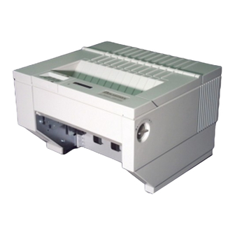
- Page 24 User’s Guide Figure 1-3: Back Printer Parts 1-10 Keypad Configuration...
-
Page 25: Install The Power Cord
Install the Power Cord Set the power switch to Off. (See Figure 1-4). Install the power cord into the printer as shown in Figure 1-4. Verify that voltage setting is correct for the application (115V-U.S.) (See Figure 1-4). CONNECTING THIS EQUIPMENT TO AN UNGROUNDED POWER RECEPTACLE CAN RESULT IN ELECTRICAL SHOCK. - Page 26 User’s Guide Figure 1-4: Install Power Cord 1-12 Keypad Configuration...
-
Page 27: Install The Ribbon Cartridge
Install the Ribbon Cartridge To prolong ribbon life, the printer is shipped without the cartridge installed. The following procedure is written for both initial installation and ribbon replacement. Press the On/Off Line key to display "off line" status. If paper is loaded, press PARK key to park the form in the tractors. - Page 28 User’s Guide Figure 1-5: Open Access Cover (Both Options) 1-14 Keypad Configuration...
- Page 29 Check the Form Thickness Adjustment Knob to be sure that it is in the first position as shown in Figure 1-6. If replacing the ribbon, the Form Thickness Adjustment Knob will automatically move away from the form when the paper is parked in the tractors.
- Page 30 User’s Guide Steps 4 and 5 are not required for initial ribbon installation. Remove the ribbon guide from printhead (lift up and rotate towards front). Remove ribbon cartridge from printer. Move the printhead to the center of the printer. 1-16 Keypad Configuration NOTE Figure 1-7: Remove Ribbon Guide...
- Page 31 PRINTHEAD GETS HOT DURING USE. USE CAUTION WHEN HANDLING THE PRINTHEAD. Tighten ribbon. Snap on ribbon guide. Remove slack from ribbon. Figure 1-8: Position Ribbon Cartridge In Printer WARNING Keypad Configuration 1-17 User’s Guide...
- Page 32 User’s Guide 10. Lower ribbon cartridge towards slots in printer. Ensure that ribbon loop is in front of platen and that ribbon is not twisted. 11. Drop the ribbon cartridge into the ribbon alignment slots. 12. If the ribbon cartridge does not seat squarely on the ribbon drive, rotate the Ribbon Advance Knob in the direction indicated by the arrow on the knob until the cartridge drops into place on the ribbon drive.
- Page 33 User’s Guide Figure 1-9: Install Ribbon Cartridge Keypad Configuration 1-19...
-
Page 34: Printer Self Test
User’s Guide Printer Self Test This test is used to verify printer operation. Before performing the printer self-test, refer to Section 3.3 Load Forms Page 3-3 for instructions on loading paper in the printer. To start the test: MARGINS ARE SET FOR 8.5” PAPER. PRINTING OFF OF FORM WILL LEAD TO PRINTER DAMAGE. - Page 35 User’s Guide Figure 1-10: Self-Test Sample Keypad Configuration 1-21...
-
Page 36: Interfacing
User’s Guide Interfacing The three types of interfaces offered by the printer are RS-232 serial, RS-422 serial, and TTL level 8-bit PC compatible, parallel interface. Serial and parallel interface connectors are provided on the rear of the printer. The 25-pin serial connector is compatible for both RS-232 and RS-422. - Page 37 Refer to the documentation for your computer to determine the type of shielded interface cable needed and any unique pin-out configuration that may be required. This information should be given to your dealer or distributor to determine the correct cable for your use. BEFORE CONNECTING THE CABLE, MAKE CERTAIN BOTH THE HOST COMPUTER AND THE PRINTER ARE...
-
Page 38: And Rs-422 Serial Interface Configuration
User’s Guide 1.10 RS-232 and RS-422 Serial Interface Configuration Set the power switch to On. Open the Keypad Door. The first menu will appear on the display. Press the Next Menu key until you have accessed Menu 5 Press the Feature Key one time to select Baud Rate Feature. - Page 39 User’s Guide 11. Close the Keypad Door to exit Setup Mode. Display will alternate: Press ‘Profile’ To Save Settings 12. Press the Profile key to permanently save the profile setting. 13. Press the On/Off Line Key to place the printer back on line. On Line Profile 1 Keypad Configuration 1-25...
- Page 40 User’s Guide 1-26 Keypad Configuration...
-
Page 41: Chapter 2. Keypad Configuration
Keypad Configuration Keypad Configuration This chapter describes the keypad, Ready LED, and LCD display. The locations of all keys and their functions are illustrated below. Figure 2-1: Keypad Configuration User’s Guide Forms Handling 2-1... -
Page 42: Ready Led
User’s Guide Ready LED The printer is equipped with one green LED indicator to signify READY status. Function of the Ready indicator is as follows: On – Printer is on line and ready to accept data. Off – Printer cannot accept data for any of the following reasons: a. -
Page 43: On/Off Line Key Function
User’s Guide On/Off Line Key Function On/Off Line key functions are the functions printed on the Keypad Door encircling the keypad. Primary key functions are used for normal operation. Setup Mode functions are active when the Keypad Door is raised and are explained in Chapter 4. Figure 2-3: Primary Keys Forms Handling 2-3... - Page 44 User’s Guide Pressing this key switches the printer between on line and off line status. This key is used in conjunction with the LCD display. The On/Off Line key is also used to continue after clearing an error condition or to acknowledge tearing off a form on a paper path change.
- Page 45 Pressing this key moves the form downward 1/144 inch for precise form alignment. When the key is pressed for more than ½ second, the paper reverse feeds continuously until the key is released. Pressing this key advances forms up to the tear bar so that the last printed form can easily be removed.
-
Page 46: Lcd Display
User’s Guide LCD Display The printer signals various messages through the LCD display. Examples are shown below: Features and Values: On Line Display: Off Line Display: Paper Out Conditions: Initial Display when Keypad Door is open: 2-6 Keypad Configuration Left Margin xxx On Line Profile 1 Off Line Profile 1 <Paper Out Main>... -
Page 47: Forms Handling
Forms Handling Recommended Types and Sizes The following are guidelines for recommended paper types and sizes for use with the printer. Continuous Forms (Main Paper Path) Width – 3 ½ to 10 5/8 inches (88.9mm to 269.8 mm) Individual Part Thickness - .005 inch maximum (.127mm) Total Form Thickness - .028 inch maximum (.711mm) Number of copies –... -
Page 48: Paper Paths
User’s Guide Paper Paths For best results, use the main paper path for thicker, stiffer forms. Figure 3-1: Paper Feed Paths 3-2 Forms Handling... -
Page 49: Load Forms
Load Forms To load the main tractor path on Dual Path printer, place alternate path tractors in center position. Main tractor doors cannot be opened with alternate tractors aligned in front. (Hint: Use least frequently changed paper in main tractors and frequently changed paper or narrow stock in the alternate path.) If both paths are used, main tractor path must be loaded first. - Page 50 User’s Guide IMPROPER RESULTING IN PRINTING PAST THE EDGE OF THE FORM CAN CAUSE DAMAGE TO THE PRINTHEAD. Position the front paper guides and rear paper supports equally across width of form. (Hint: For easy movement, grab the front paper guides and push up while sliding.) Proper position of paper supports will help prevent jams.
- Page 51 Open the right tractor door and load the paper into the right tractor. Compare position of paper in left and right tractors and adjust as necessary to keep paper even. Improper alignment of paper feed holes (Figure 3-3) will result in paper jam. Close tractor door. If necessary, move the right tractor to the right to slightly tension the paper.
- Page 52 User’s Guide Figure 3-3: Forms Loading (Sheet 1 of 2) 3-6 Forms Handling...
- Page 53 User’s Guide Figure 3-3: Forms Loading (Sheet 2 of 2) Forms Handling 3-7...
- Page 54 User’s Guide Make sure the continuous forms are located directly under the tractors. The paper must hang straight. Incorrect positioning of the forms may cause a paper jam. Figure 3-4: Placement of Continuous Forms 3-8 Forms Handling...
- Page 55 Set the power switch to On. (For cut sheet forms, go directly to Step 10). After the printer initializes, press the Load key to load paper. When the load key is pressed, the Form Thickness Adjustment knob will automatically move to the correct location.
- Page 56 User’s Guide 10. Set left paper guide window at the “0” mark. Grab form in center with one hand and align left edge of form against left paper guide. (Do not fully insert form.) Use other hand to snug right paper guide against right edge of form. (Do not buckle forms between paper guides.) Push in form until leading edge is squarely against rollers.
- Page 57 User’s Guide NOTE If forms length is between 4.5” and 6.0”, verify that the Vertical Gap Position Feature is set to 0.0” (located under M8 Form Thickness in the setup mode). See Section 4.6 for further instructions on how to change this setting.
- Page 58 User’s Guide 11. Set form length, right and left margins. To set form length, first measure the length of the form (in inches) and multiply this value by the vertical lines per inch. For example: if the form length is 11 inches and the vertical pitch is 6 lines per inch, then the form length would be: 11 inches x 6 lines per inch = form length 66 lines To set the form length, open the keypad door and press the Quick Access key until...
-
Page 59: Top Of Form Adjustment
Top of Form Adjustment (Adjusting First Printline Location) Perform this adjustment immediately after loading paper to determine where the first line will print. Making this adjustment while printing on the page allows fine alignment without resetting line count. When paper is loaded into the printer, the printer automatically positions the paper to print on the first line of the form. - Page 60 User’s Guide Figure 3-9: Set First Print Line 3-14 Forms Handling...
-
Page 61: Tear Off Adjustment
Tear Off Adjustment In a demand document application, the form will be advanced to a tear off position when the Tear Off key is pressed. When the forms are in this position, the last printed form may be removed by pulling the perforation against the tear edge of the cover. If the perforation does not come to rest at the tear edge, the tear off distance may be adjusted as follows: Press the Tear Off key. - Page 62 User’s Guide For cut sheet units, to avoid excessive opening and closing of the Top Exit Cover when alternating between short cut sheet forms and continuous tractor forms, adjust the tear bar (metal edge located immediately above top rollers) by using this procedure. (The value will be about 1-40/144 inches.) The function of the Tear Off key is affected by the Manual Tear feature located in the...
- Page 63 User’s Guide Figure 3-10: Printer Located Under Countertop Forms Handling 3-17...
-
Page 64: Form Thickness Adjustment
User’s Guide Form Thickness Adjustment The distance from the printhead to the paper is automatically changed to accommodate the thickness of the forms whenever the unit is powered up or paper is loaded. The adjustment can be manually changed using the knob on the right-hand side of the printer, or adjusted automatically by changing the feature setting as outlined below: IMPROPER ADJUSTMENT... - Page 65 b. Press the Next Menu key to access Menu 8, Form Thickness. c. Press Feature key to obtain this display. Use the Value keys to adjust the form thickness gap. Form thickness setting will be stored in memory. a. Press the Value key once or twice to reduce the form gap (moves the printhead closer to the form) if there is light print.
- Page 66 User’s Guide Run another print sample. Return to Step 2 and repeat until print quality is acceptable. Manually adjust the form thickness setting as follows (temporary adjustment, not stored in memory): a. Turn knob clockwise one click until print quality is acceptable. b.
-
Page 67: Heavy Forms Adjustment
Heavy Forms Adjustment The Heavy Forms feature allows the printhead to be positioned horizontally on the form to avoid labels, paper perforations or other variations in form thickness that can cause paper handling issues. This feature becomes active when the paper moves more than 0.5 inches. The default location of the printhead is 2 inches from the left side of the printer. -
Page 68: Changing From Main Paper Path To Alternate Path
User’s Guide Changing From Main Paper Path to Alternate Path If continuous forms are presently loaded in the printer, you may change to the alternate paper path by proceeding as follows: (For cut sheet models, just insert the form. The following steps will be automatically executed by the printer.) Press the On/Off Line key to take printer off line. - Page 69 User’s Guide Figure 3-12: Main and Alternate Paper Paths (Cut Sheet not Shown) Forms Handling 3-23...
-
Page 70: Changing From Alternate Paper Path To Main Paper Path
User’s Guide Changing From Alternate Paper Path to Main Paper Path If paper is loaded in the alternate printer path, you may change to the Main Paper Path by proceeding as follows: Press the On/Off Line key to take printer off line. Press the Tear Off key to advance form to tear off point. -
Page 71: Paper Out Condition
3.10 Paper Out Condition When the printer runs out of paper, the following messages will appear in the display depending on paper path selected: Remove last printed form from paper path by using Form Feed key. Load continuous forms. Refer to Page 3-3. Press the On/Off Line key to go back on line. -
Page 72: Automatically Changing Paper Paths On Paper Out
User’s Guide 3.11 Automatically Changing Paper Paths On Paper Out The printer may be configured to automatically change paper paths during a paper out condition. This may be useful in applications where the printer is unattended or installed at a remote location. -
Page 73: Selecting Paper Paths Using The Profile Key
3.12 Selecting Paper Paths Using the Profile Key Each Profile contains a ‘Path’ feature which specifies the (Main, Alt, Either) paper path. When a profile is selected, the paper path may be automatically changed or the operator may be asked to load a new form in the currently selected paper path. The action taken depends on the value of the ‘Path’... - Page 74 User’s Guide Example using same path: The current profile is named “Invoices” and the paper path selected by that profile is alternate. The new profile named “Memos” specifies the same path (Alt). After selecting profile “Memos” and the printer has successfully parked the invoices, the following message will be displayed: After loading memos into the alternate path, press the Load key.
-
Page 75: Selecting Paper Paths From The Host Computer Using Dpcl Command
3.13 Selecting Paper Paths From the Host Computer Using DPCL Command In demand document applications, the paper path may be selected by using Downline Printer Control Language (DPCL) sequences to select the active Profile 1-4. This command is available in all emulation modes. Indicating a profile using DPCL commands will allow paper path selection from the host computer. - Page 76 User’s Guide The DPCL sequence to change profiles is active in all emulations. Select Profile (form) <n> CODE FORMAT ASCII: ESC DECIMAL: HEXADECIMAL: Description: This command is used to select Profile n where values of n range from 1 to 4. The Paper Path may be selected by the Host Computer by configuring the ‘Path’...
-
Page 77: Chapter 4. Features And Profiles
Features and Profiles Features This chapter describes and explains the various user programmable features of the printer. Using the keypad, the printer can be easily configured to operate in a variety of host environments and provide print for common applications such as reports, checks, invoices, and labels. -
Page 78: Profiles
Profiles A unique benefit of this printer is its ability to store the feature settings for commonly used applications in what is called a Profile. Up to four profiles may be named, stored in the printer’s non-volatile memory, and recalled with a few key strokes. This avoids time consuming setup and reprogramming each time the application changes. - Page 79 In this sample, change from printing “Reports” to “Checks” as follows: Take printer off line by pressing the On/Off Line key. Park current form. Change to desired profile, in this case “checks”. Load the appropriate forms (“checks”). Place unit on line. For an application that is not stored in a profile, call up the profile whose features most closely match the application and reprogram only the features requiring change.
-
Page 80: Setup Mode Key Functions
User’s Guide Setup Mode Key Functions To change features, open the Keypad Door to enter Setup Mode. Figure 4-1 shows the Setup Mode keys and their respective functions. A brief description of each key function follows: Figure 4-1: Setup Mode Keys 4-4 Features and Profiles... - Page 81 The Next Menu key provides access to a specific group of features. Pressing this key steps through the printer features by menu. This prevents having to “cycle through” the entire list using the Feature key in order to get to the desired feature.
-
Page 82: Lcd Display
User’s Guide LCD Display In Setup Mode, the LCD display provides the following information: Form Length 88 Feature Name and Value: M1 PAGE FORMAT Menu Names: Self Test Diagnostic Tests: 4-6 Features and Profiles... -
Page 83: Profile Feature Listing
Profile Feature Listing To print a listing of the feature settings of a particular profile, follow the steps below: Make certain 20 column or wider paper is loaded in the printer. Press the On/Off Line key to take the printer off line. Before entering Setup Mode, press the Profile key until it displays the profile you wish to print. -
Page 84: Changing Features In A Profile
Changing Features in a Profile Feature settings in a profile may be changed through the keypad by following the steps below: Press the On/Off Line key to take the printer off line. Press Park key to park paper. Press the Profile key to select profile being changed. Open the Keypad Door. - Page 85 Repeat Steps 5 through 8 as necessary until all features are correctly set for your application. 10. Close the Keypad Door to exit Setup Mode. The alternating display will read: To answer “Yes”, press the Profile key. This will permanently record the change in non-volatile memory for that profile.
- Page 86 As an example, assume the profile you are presently using defines the lines per inch as 6. To permanently change the lines per inch to 8, proceed as follows: Press the On/Off Line key to take the printer off line. Press Park key to park paper.
-
Page 87: User Programmable Features
User Programmable Features Menu 1: Page Format Printer Displays Lines/Inch Form Length Top Margin Bottom Margin Left Margin Right Margin Values Vertical pitch for printing text in lines per inch. Lines per page resets top and bottom margins. Value cannot exceed bottom margin. Number of lines from the top-of-form and the first print line. - Page 88 Menu 1: Page Format (Cont’d) Printer Displays Clear Horz Tabs Horz Tab ### xxx Clear Vert Tabs Vert Tab ### xxx 4-12 Features and Profiles Values Clear Horizontal Tabs Pressing the Enter key will clear all horizontal tabs. Set/Clr Horizontal Tabs Pressing the Value key selects the column (#) where a horizontal tab may be set or cleared.
- Page 89 Menu 2: Forms Control Printer Displays Load ###/144” Load Crg Mov Horz Adj xxx/144” Tear x xxx/144” Values 0 0/144 This feature is used to align the first printline of a form and the printhead. This feature is normally set using the Adjust Form key. This feature is active only during paper loading.
- Page 90 Menu 2: Forms Control (Cont’d) Printer Displays Manual Tear Manual Time ###s Auto Tear 4-14 Features and Profiles Values The printer will perform a form feed before moving to the tear position after pressing the Tear Off key. The printer will move to the tear position after printing crosses the next forms boundary after pressing the Tear Off key.
- Page 91 Menu 2: Forms Control (Cont’d) Printer Displays Auto Time ###s HF: Pos crg x.x” HF: xxxxxxxxxxxx Values The time in seconds that the form will be in the tear position after more data is sent to the printer. This feature works only when the Auto Tear feature is ON.
- Page 92 Menu 2: Forms Control (Cont’d) Printer Displays Path xxxxx Paper Speed 4-16 Features and Profiles Values Either Allows the current profile to be paper path Main specific. Alt. This feature controls the paper feed speed in inches per second. Slower speeds may improve paper handling of certain forms.
- Page 93 Menu 3: Personality Printer Displays Emulate xxxxxxxx Font xxxxxxxxxx Values IBM Pro This feature selects the desired emulation. IBM Grph. LA 120 Escape sequences for each emulation are listed Epson FX in the “Programmer’s Manual.” DS-180 Display Hex display feature, see “Troubleshooting and Maintenance”...
- Page 94 Menu 3: Personality (Cont’d) Printer Displays Set xxxxxxxxx Nat. xxxxxxxx IBM CHAR Set Print Zero as 4-18 Features and Profiles Values 7 Bit ASCII Refer to “Programmer’s Manual” for DEC Supplmt1 character tables. IBM Code 437 IBM Code 850 Epson Italic Epson Graph Epson Ital/Gr All nationalities are available in all symbol...
- Page 95 Menu 4: Printer Control Printer Displays Auto LF Auto CR Wrap Print xxxxxxxx Auto Path SW Vert Graphic Horz Graphic Power Up xxxxxxxx Values Disable No line feed with carriage return. Enable Performs a line feed with carriage return. Disable No carriage return with line feed.
- Page 96 Menu 4: Printer Control (Cont’d) Printer Displays Buffer Size xxxx Window Size xxxx Ribbon Dble Strike 4-20 Features and Profiles Values Specifies the size of the data buffer. Lower limit of this range may be limited by “Window Size” feature. Depends on buffer option installed Window (FIFO size) Specifies how many bytes of data must be...
- Page 97 Menu 4: Printer Control (Cont’d) Printer Displays DGCL xxxxxxx Exit Mode xxxxxx Command Char Overlap xxxxxxx DW Term See Chapter 6 in Programmer’s Manual for barcode programming. Values Disable Disables recognition of Barcode Transparency commands Enable Enable recognition of Barcode Transparency Commands Adjust Adjust the form to the next logical line feed...
- Page 98 Menu 5: Serial Control Printer Displays Baud Rate xxxx Serial xxxxx Parity xxxxx Data Bits xxxxxxx 4-22 Features and Profiles Values Refer to the documentation of your host computer to determine the baud rate. 1200 1800 2400 4800 9600 19.2k RS-232 Selects serial configuration RS-422...
- Page 99 Menu 5: Serial Control (Cont’d) Printer Displays xxxxxxx Handshk xxxxxxx X-ON Ctrl X-OFF Ctrl Modem Ctrl Values Hardware Handshaking Enable DTR (Data Terminal Ready) Busy on when: Buffer filled to high water mark Printer off line Paper out condition Error conditions Busy off when: Buffer below low water mark Disable...
- Page 100 Menu 6: Parallel Control Printer Displays Handshk on xxxx Ack xxxxxx Busy xxxxxxx Parallel xxxxxxx 4-24 Features and Profiles Values Parallel interface handshaking Busy Active when: < or > Buffer filled to high water mark Printer off line Paper out condition Error conditions Inactive when: Buffer below low water mark...
- Page 101 Menu 7: Profile Control Printer Displays Rename: xxxxxxxx Save Profile Reset Profile SER Prt PAR Prt Port Time ###s Values 0 ….. 9 Profile Name A ….. Z This feature allows you to give the current profile a customized name. a …..
- Page 102 Menu 7: Profile Control (cont’d) Printer Displays Max Profile 4-26 Features and Profiles Values This feature is used to limit the number of active profiles, thus eliminating the need to cycle through unused profiles. This feature is universal and can be changed in any profile.
- Page 103 Menu 8: Form Thickness Control Printer Displays Auto Form Gap Quiet or Whisper Adj. Form Gap Hor Gap Pos xx.x VR Gap Pos xx.x Values Allows the user to perform an immediate automatic form thickness adjustment. Thickest part of form should be used when making this adjustment.
-
Page 104: Menu 9: Diagnostics
Menu 9: Diagnostics Printer Displays Print Profile P/N: ###### Test Printhead Run Mode test Run Self Test 4-28 Features and Profiles Values Pressing the Enter key will print the current profile features. Paper must be loaded in the printer before pressing the Enter key. - Page 105 User’s Guide Menu 10: System Control NOTE Refer to Appendix D for instructions on accessing Menu 10. Features and Profiles 4-29...
- Page 106 User’s Guide 4-30 Features and Profiles...
-
Page 107: Chapter 5. Troubleshooting And Maintenance
Troubleshooting and Maintenance Scheduled Maintenance This chapter provides scheduled maintenance and troubleshooting procedures that can be performed by the operator. A qualified technician should perform any troubleshooting or maintenance beyond the level presented in this chapter. MAKE CERTAIN THE PRINTER IS DISCONNECTED FROM THE AC POWER SUPPLY BEFORE REACHING INTO THE UNIT TO PERFORM ANY CLEANING OR... - Page 108 User’s Guide Use a small vacuum cleaner to remove dust from the carriage, platen, paper tractors, paper out sensors, and printer throat. A dry, lint-free cloth may be used to clean accumulated dirt from the carriage shafts and the platen. Figure 5-1: Cleaning the Printer 5-2 Troubleshooting and Maintenance...
-
Page 109: Error Message
Error Message Paper Out Condition (Main Tractors) When the printer runs out of paper, the following message will appear in the display: The printer will automatically go off line when the paper supply is depleted. To recover from a paper out condition: Load paper into the main tractors. - Page 110 User’s Guide Paper Out Conditions (Alternate Tractors) When the alternate tractors run out of paper, the following message will appear in the display: Load paper into Alternate tractors. Press Load key to load forms. Press On/Off Line key to continue. The error message will be cleared from the display after paper is loaded.
-
Page 111: Paper Jam
Paper Jam Paper jams may occur for several different reasons including: incorrect forms loading, form thickness adjustment set too close, or form out of specification. Check the value of the features that may affect form thickness adjustment: horizontal gap, vertical gap, heavy forms, and adjust form gap. - Page 112 User’s Guide Carriage Jam If the carriage is unable to move because of foreign objects in the printer or because of mechanical failure, the following messages will alternate in the display: To recover from this error condition: Press the On/Off Line key to take the printer off line. Open the Access Cover.
-
Page 113: Keypad Lockout
User’s Guide Keypad Lockout The following message is displayed momentarily after pressing a key which has been locked out or delayed: >> Key Locked << This feature can be changed by using the instructions located in Appendix D. Troubleshooting and Maintenance 5-7... -
Page 114: Printer Diagnostics
User’s Guide Printer Diagnostics Printer Diagnostics The following printer diagnostics are available to aid in troubleshooting printer malfunctions. They are accessed while in the Setup Mode under Menu 9: Diagnostics. To initiate these diagnostics, perform Steps 1-5 Paper must be loaded prior to performing printer diagnostics. -
Page 115: Print Profile
User’s Guide Print Profile This test will print a complete listing of feature settings for the current profile. This is normally used to obtain a quick list of the printer feature settings that can be compared with the computer system. Figure 5-4: Print Profile Troubleshooting and Maintenance 5-9... - Page 116 User’s Guide Figure 5-4 (cont’d): Print Profile 5-10 Troubleshooting and Maintenance...
- Page 117 User’s Guide P/N: 104217 – xx (Firmware Part Number) This test is normally used by service personnel to determine what level and type of firmware is installed in the printer. The test is included in the “Print Profile ” feature, Figure 5-4, M9 Diagnostics.
-
Page 118: Test Printhead
User’s Guide Test Printhead This test verifies that the individual printhead impact wires and the controlling electronics are operating properly. It may be used to identify the cause if dots are missing on the print out. In this test, one complete line is printed using each wire in the printhead. The wire is noted in the test print out. -
Page 119: Run Mode Test
User’s Guide Run Mode Test This test (requiring 80 column paper) will print the current Symbol set in all fonts available in the printer. Troubleshooting and Maintenance 5-13... -
Page 120: Run Self Test
User’s Guide Run Self Test This test (requiring 80 column paper) will print an ASCII ripple pattern and will test the internal logic of the printer. If this test runs, the printer has passed all internal diagnostics. 5-14 Troubleshooting and Maintenance... -
Page 121: Display Mode
User’s Guide Display Mode This test (requiring 80 column paper) is accessed while in Setup Mode under M3 Emulate. It is used to aid in program debugging or problem isolation. When Enabled, all data being sent to the printer from the computer is passed through the normal printer logic and printed in a hex dump format. -
Page 122: Troubleshooting
User’s Guide Troubleshooting Please read this section before continuing to symptom analysis. The following diagnostic tests are used to aid in isolating possible printer malfunctions. These tests will assist the operator in determining printer/host problems. information for printer error recovery is described under Error Messages. For host to printer communication problems, it is suggested that the operator read the Interface Functional Description of this manual prior to symptom analysis. -
Page 123: Troubleshooting Table
Troubleshooting Table Symptom No Host Communication Serial No Host Communication Parallel No Power/Blank Display Corrective Action Verify properly selected profile. Check interface cable (pin outs), cable connections, or try a new cable. Verify emulation selected. Verify baud rate, serial type (RS-232, RS-422), parity, data bits, DTR, handshaking Is serial port disabled? Reset profile and re-setup the printer. - Page 124 User’s Guide Symptom Paper Feeding Problems Tractors 5-18 Troubleshooting and Maintenance Corrective Action Verify power plug connection to the printer. Verify paper tension. Adjust tractors if paper is too tight or too loose causing buckling (See Section 3.3) Make sure the paper holes are aligned properly in tractors. Equally space rear paper supports and front paper guides between tractors.
- Page 125 Symptom Paper Feeding Problems Cut Sheet * Skewed Print On Cut Sheet Forms Improper Print Alignment between first and last sheet of form (Delamination) * To avoid vertical inaccuracy, do not print using Double High, Double Strike, Superscript, or Twelve dot high characters over the last 2 inches of a cut sheet form.
- Page 126 User’s Guide Symptom Carriage Jam No Print Short Ribbon Life Prints Garbage Parallel 5-20 Troubleshooting and Maintenance Corrective Action Turn off power, open front Access Cover, and check for foreign objects. Verify label is not stuck to the ribbon guide. Verify form thickness setting.
- Page 127 Symptom Prints Garbage Serial Loss of Data Buffer Overflow Parallel Loss of Data Buffer Overflow Serial Printhead Moves but No Printing Occurs Printhead Pauses at End of Print Lines Corrective Action Verify properly selected profile. Check interface cable (pin outs), cable connections, or try a new cable.
- Page 128 User’s Guide Symptom Printer Will Not Switch Paths First Print Line Location is Wrong Print Contrast on Last Sheet is Too Light Printer is Too Noisy 5-22 Troubleshooting and Maintenance Corrective Action Change the Path Value to “Either” under M2: Forms Control.
-
Page 129: Appendix A. Printer Specifications
A. Printer Specifications A.1 Printer Characteristics Printhead: 9 wire with a rated life of 200,000,000 draft characters. Maximum Line Length: Main Tractor Path 8.8 inches (223mm) (88 columns @ 10 cpi) Alternate Tractor Path 8.8 inches (223mm) (88 columns @ 10 cpi) Vertical Pitch: 1, 2, 3, 4, 6, 8 and 12 lines per inch and variable spacing, depending on the emulation. -
Page 130: A.3 Font Specifications
User’s Guide A.3 Font Specifications Available Fonts/Typefaces: 10, 12*, 13.2, 15, 16.5, Draft 10, 12, 13.2, 15, 16, 16.5, Courier Prestige Helvetica OCR A OCR B * 9 x 9 at 333 cps Graphic Densities: Horizontal Dots/Inch Printer Specifications Pitches Matrix (H x W) 17.16, 18, 20 17.16, 18, 20... - Page 131 International Character Sets : Epson Nationalities France Germany U. K. Denmark I Sweden Italy Spain I Japan Norway Denmark II Spain II Latin America DEC Nationalities U. K. Finland Sweden Norway/Denmark Germany France Printer Specification A-3 User’s Guide...
-
Page 132: Paper Feed Specifications
User’s Guide A.4 Paper Feed Specifications Paper Types: Main Tractor: 3 ½ inches to 10 5/8 inches (88.9 mm to 269.8 mm), 1 to 9 part, .028 inches (.127 mm) max. thickness. Individual parts not to exceed .005 inches (.711 mm) thickness without factory approval. -
Page 133: Forms Mode Change
A.5 Forms Mode Change Parking Forms : The forms are reverse fed into the tractors, so that the alternate paper path may be selected. The new forms are then reloaded to the previously set top-of-form and top margin. Tear Off: A key may be used to advance the forms a predefined distance, so the last printed form can be removed without wasting the next form. -
Page 134: Operator Panel Functional Description
User’s Guide A.7 Operator Panel Functional Description Display Description: 1 line by 16 character LCD. In addition, an LED is used to indicate READY (On Line) status. Keyswitch Layout: 8 keys A.8 Ribbon Cartridge/Drive Stationary cartridge with an average life of 7-10 million characters (depending upon printing application). -
Page 135: Electrical
A.10 Electrical Power Requirements: 97 V to 132 V, 57 to 63 Hz 195 V to 264 V, 47 to 53 Hz A.11 Shock and Vibration The printer meets NSTA pre-shipment requirements. A.12 Environmental Temperature: Non-operating: -30° to 180° F (-34° to 82° C) Operating: 40°... -
Page 136: Compliances
User’s Guide A.13 Compliances This unit will comply with the following at the time of production. Safety: UL 1950 CSA C22.2 No 950M-1989 EN 60950 IEEE587 EN 50082-1 EMI: FCC Class A EN 55022 Class A VDE Class B Printer Specifications... -
Page 137: Appendix B. Interface Specifications
B. Interface Specifications B.1 Parallel Interface Data Transmissions: 7 or 8 bit Synchronization: Externally supplied Data Strobe Handshaking: Acknowledge (Busy before Acknowledge or Busy after Acknowledge) Busy (Acknowledge before Busy or Acknowledge after Busy) Logic Level: Input data and all interface signals are TTL compatible. Two output signals control the handshaking on the parallel interface, the BUSY signal and the ACKNOWLEDGE signal. - Page 138 User’s Guide CONDITION READY FIFO FULL PAPER OUT CRG JAM OFF LINE FATAL ERROR + Active high - Active low Interface Specifications SIGNAL +BUSY +PAPER- HIGH HIGH HIGH HIGH HIGH HIGH +SELECT -ERROR HIGH HIGH HIGH HIGH HIGH HIGH...
- Page 139 User’s Guide Interface Specifications B-3...
- Page 140 User’s Guide The following diagram illustrates the signal timing of the parallel interface when Acknowledge is issued after busy. Figure B-2: Signal Timing Pattern (Sheet 1) Interface Specifications...
- Page 141 User’s Guide The following diagram illustrates the signal timing of the parallel interface when Acknowledge is issued before busy. Figure B-2: Signal Timing Pattern (Sheet 2) Interface Specifications B-5...
-
Page 142: Parallel Interface Enable/Disable
User’s Guide B.2 Parallel Interface Enable/Disable Set the power switch to On. Press the On/Off Line key. Open the Keypad Door. The first menu will appear on the display. Press the Next Menu key until you have accessed Menu 6. The display will appear as shown: Press the Feature key to select the Parallel feature. -
Page 143: Serial Interface
B.3 RS-232 Serial Interface Data Transfer Rates (Baud Rate ): 2400 4800 9600 1200 19200 1800 Synchronization: Start-Stop Bits Data Format: Start Bit: Data Bits: 7 or 8 Parity: Odd, even or no parity Stop Bit: 1 for reception 1 for transmission If the host serial interface is configured for 7 Bit data with no parity, data from host computer must contain two stop bits. - Page 144 User’s Guide When the printer is ready for more data, it will transmit the DC1 (X-ON) character. ETX/ACK: The host will include the ETX character at the end of a string of data. When the printer detects the ETX character, it transmits an ACK character to the host, indicating it is ready for more data.
-
Page 145: Modem Control
SIGNAL NO MODEM CONTROL When the printer is ready to accept data, this line will be high (+EIA LEVEL). This line will go low (-EIA LEVEL) when: a. Print buffer is nearly full (within 512 bytes) b. Paper out condition exists. c. -
Page 146: Serial Interface Selection
User’s Guide B.4 Serial Interface Selection Set the power switch to On. Press the On/Off Line key. Open the Keypad Door. The first menu will appear on the display. Press the Next Menu key until you have accessed Menu 5. The display will appear as shown: Press the Feature Press the Value... - Page 147 RS-232 Serial Interface Connector Pin Assignment Frame Ground Transmitted Data Received Data Request to send Clear to Send Data Set Ready Signal Ground Data Carrier Detects No Connect No Connect Data Terminal Ready No Connect No Connect Reserved Reserved Reserved Reserved Reserved Reserved...
- Page 148 User’s Guide RS-422 Serial Interface Connector Pin Assignment Frame Ground Reserved Reserved Reserved Reserved Reserved Signal Ground Reserved No Connect No Connect No Connect No Connect No Connect Transmitted Data (+) Transmitted Data (-) Received Data (+) Received Data (-) Data Terminal Ready (+) Data Terminal Ready (-) Reserved...
-
Page 149: Default Tables
C. Default Tables Profiles are user definable sets of default parameters that can be used to setup the printer for predetermined function(s). All profiles reside in the non-volatile printer memory and are retained when the printer is powered off. configuration is loaded into the printer control system. All profiles are defaulted to the same factory settings. -
Page 150: Forms Control
C.2 Menu 2: Forms Control Feature Defaults Load 0 72/144” Load Crg Mov Horz Adj 0/144” *Tear x x/144” Manual Tear Manual Time Auto Tear Auto Time HF: Pos Crg 2.0” HF: On Feed> 0.5” Path Either Paper Speed * Varies depending on Top Access cover configuration. C.3 Menu 3: Personality Feature Defaults... -
Page 151: Printer Control
C.4 Menu 4: Printer Control Feature Defaults Auto LF Disable Auto CR Disable Wrap Enable Print Bidirect Auto Path SW Vert Graphic Horz Graphic Power Up On Line Buffer Size Window Size Dble Strike DGCL Enable Exit Mode Adjust Command Char Overlap Disable Profile 1... -
Page 152: Parallel Interface
C.5 Menu 5: Serial Interface Feature Defaults Baud Rate 9600 Serial RS-232 Parity None Data Bits Enable Handshk X-On/X-Off X-On Ctrl Single X-Off Ctrl Single Modem Ctrl C.6 Menu 6: Parallel Interface Feature Defaults Handshak On Busy Before Busy Enable Parallel Enable Default Tables... - Page 153 C.7 Menu 7: Profile Control Feature Defaults Rename: Profile 1 Save Profile Reset Profile SER Prt PAR Prt Port Time Max Profiles *** These features cannot be user defined. C.8 Menu 8: Form Thickness Control Feature Defaults Auto Form Gap Quiet High Adj.
-
Page 154: Menu 9: Diagnostics
C.9 Menu 9: Diagnostics Feature Defaults Print Profile P/N: ##### Test Printhead Run Mode Test Run Self Test *** These features cannot be user defined. To change these settings, follow the direction in Chapter 4 “Features”. It is suggested that the user execute the “Print Profile ”... -
Page 155: Menu 10 System Control
C.10 Menu 10 System Control Feature Defaults Reset NVRAM Key, Lockout All Unlocked Reset Quick List Font DP 10 Lines/Inch Form Length Left Margin Right Margin Add Quick Ftr Delete Quick Ftr Ribbon Life Replace Rib Check Rib *Config * Depends on mechanical configuration. Resets to ‘Tractor’ only when new firmware is installed. - Page 156 User’s Guide Default Tables...
-
Page 157: Appendix D. System Administration Features
D. System Administration Features D.1 Features Available In System Control Menu This appendix describes how to access features that are not normally available while the printer is in Setup Mode. These features are found in Menu 10: System Control. By accessing this menu you can: Reset all profiles and system information to factory defaults. -
Page 158: Menu 10: System Control
User’s Guide D.2 Menu 10: System Control Displayed Function Values Reset Printer NVM Reset Key Lock System Administration Features Description of Features Pressing the Enter key will reset all profiles to their factory defaults. This will also set top-of-form to the current position and the printhead to platen default position. - Page 159 Menu 10: System Control Displayed Function Values Key Lock Functions Off Line Load/FF Setup Adj Up Adj Down Tear Off Line Feed Unlock Profile Lock Park/Path Description of Features Use the Value up/down keys to scroll through the available key list. If the Enter key is pressed, the Values “lock”...
- Page 160 User’s Guide Menu 10: System Control Displayed Function Values Reset Quick List Add Quick FTR Delete Quick FTR Ribbon Life 1- 50M Replace Rib 1 to 100 Check Rib 1 to 100 Config Tractor Trac-Fric Dual Trac Trac Roll System Administration Features Description of Features Resets the list of features accessed by the Quick Access key to the default features.
-
Page 161: Key Functions That Can Be Locked
D.3 Key Functions That Can Be Locked Displayed Function Off Line Disables the ability to place the printer Off Line. This function is disabled only when paper is properly installed in the printer. Profile Select and Park keys are also disabled because they are only active when the printer is off line. - Page 162 User’s Guide System Administration Features...
-
Page 163: Appendix E. Ascii Conversion Chart
E. ASCII Conversion Chart ASCII DECIMAL VALUE ASCII VALUE Space " & DECIMAL VALUE VALUE ASCII Conversion Chart E-1... - Page 164 ASCII Conversion Chart (Cont’d) ASCII DECIMAL VALUE < > E-2 ASCII Conversion Chart ASCII VALUE DECIMAL VALUE VALUE...
- Page 165 ASCII Conversion Chart (Cont’d) ASCII DECIMAL VALUE ASCII VALUE DECIMAL VALUE VALUE ASCII Conversion Chart E-3...
-
Page 167: Appendix F. Ascii Character Sets
ASCII Character Sets ASCII Character Sets A Character Set is a collection of characters (i.e. letters, numbers, and symbols) organized into a “Set” where each character is assigned a unique code. Documax supports the following Character Sets that are selected automatically when the emulation is selected. To select a Character Set different from the default select the emulation then character set. -
Page 168: Bit Ascii Character Set
User’s Guide 7 Bit ASCII Character Set F-2 ASCII Character Sets... - Page 169 User’s Guide 7 Bit ASCII Character Set (Cont’d) ASCII Character Sets F-3...
-
Page 170: Ibm Code Page 437 Symbol Set
User’s Guide IBM Code Page 437 Symbol Set F-4 ASCII Character Sets... - Page 171 User’s Guide IBM Code Page 437 Symbol Set (Cont’d) ASCII Character Sets F-5...
-
Page 172: Ibm Code Page 850 Symbol Set
User’s Guide IBM Code Page 850 Symbol Set F-6 ASCII Character Sets... - Page 173 User’s Guide IBM Code Page 850 Symbol Set (Cont’d) ASCII Character Sets F-7...
-
Page 174: Epson Italic Symbol Set
User’s Guide Epson Italic Symbol Set F-8 ASCII Character Sets... - Page 175 User’s Guide Epson Italic Symbol Set (Cont’d) ASCII Character Sets F-9...
-
Page 176: Epson Graphics Symbol Set
User’s Guide Epson Graphics Symbol Set F-10 ASCII Character Sets... - Page 177 User’s Guide Epson Graphics Symbol Set (Cont’d) ASCII Character Sets F-11...
-
Page 178: Epson Italic Graphics Symbol Set
User’s Guide Epson Italic Graphics Symbol Set F-12 ASCII Character Sets... - Page 179 User’s Guide Epson Italic Graphic Symbol Set (Cont’d) ASCII Character Sets F-13...
-
Page 180: Dec Supplemental Symbol Set
User’s Guide DEC Supplemental Symbol Set F-14 ASCII Character Sets... - Page 181 User’s Guide DEC Supplemental Symbol Set (Cont’d) ASCII Character Sets F-15...
-
Page 182: Nationality Overlay Character Set
User’s Guide Nationality Overlay Character Set F-16 ASCII Character Sets... -
Page 183: G.1 Epson Fx
G. Escape Sequence Quick Reference G.1 Epson FX The following is a listing of the commands and their functions. For complete sequence, see the Programmer’s Manual. ASCII Command Terminates horizontal and vertical tab escape sequences. Sounds the printer buzzer. Backspace. Horizontal tab. - Page 184 User’s Guide Epson FX (Cont’d) ASCII Command ESC ! Master Print mode selection ESC # Cancel Most Significant Bit (MSB) function. ESC % Select character set from ROM or from RAM. ESC & Define User-defined characters in RAM ESC * Select Graphic mode.
-
Page 185: Epson Fx
Epson FX (Cont’d) ASCII Command ESC @ Resets printer. ESC A Set line spacing to n/72 inch. ESC B Set vertical tabs. ESC C Set forms length in lines. ESC C Set forms length in inches when first variable is a null. ESC D Set horizontal tab. - Page 186 User’s Guide Epson FX (Cont’d) ASCII Command ESC T Cancel Superscript or Subscript characters. ESC U Select/Cancel Unidirectional print mode. ESC W Select/Cancel Enlarged print mode. ESC Y Select high speed double-density graphics. ESC Z Select quadruple-density graphics. ESC ^ Select 9-pin graphics.
-
Page 187: Ibm Proprinter
G.2 IBM Proprinter ASCII Command Terminates horizontal and vertical tab escape sequences. Sounds the printer buzzer. Backspace. Horizontal tab. Line feed. Vertical tab. Form feed. Carriage return. Shift out. Selects Double wide mode for the current line. Shift in. Selects condensed printing. Device control 1. - Page 188 User’s Guide IBM Proprinter (Cont’d) ASCII Command ESC 5 Select/Cancel automatic line feed. ESC 6 Select character set 2. ESC 7 Select character set 1. ESC 8 Disable paper out detector. ESC 9 Enable paper out detector. ESC : Select 12 characters per inch. ESC <...
- Page 189 IBM Proprinter (Cont’d) ASCII Command ESC N Set perforation skip to n lines. ESC O Disable perforation skip mode. ESC P Select/Cancel proportional printing. ESC Q Disable the printer. ESC R Reset tabs to default settings. ESC S Select Superscript or Subscript characters. ESC T Cancel Superscript or Subscript characters.
-
Page 190: Dec
User’s Guide G.3 DEC LA-120 ASCII Command Null character. Sounds the printer buzzer. Backspace. Horizontal tab. Line feed. Vertical tab. Form feed. Carriage return. Cancel. Cancel text in the print buffer. Introduces an escape sequence. ESC (A Select UK character set language. ESC (B Select USA character set language. - Page 191 DEC LA-120 (Cont’d) ASCII Command ESC H Set horizontal tab at current column. ESC J Set vertical tab at current line. ESC 2 Clear all horizontal tabs. ESC [4 Clear all vertical tabs. ESC [n a Advance by n columns. ESC [c Request for product ID.
- Page 192 User’s Guide DEC LA-120 (Cont’d) ASCII Command ESC [;n s Set right margin to n. ESC [0;n s Set right margin to n. ESC [n u Set horizontal tab at column n. ESC [n1;n2..;n16u Set horizontal tabs at column n1….n16. ESC [n v Set vertical tab at line n.
- Page 193 DEC LA-120 (Cont’d) ASCII Command ESC [5z Select 3 lines per inch. ESC [6z Select 4 lines per inch. ESC [n‘ Go to column n. ESC L Set horizontal tab at current column. ESC [nt Set form length to n. Cause no printer operation.
-
Page 194: Optional
User’s Guide G.4 TI-885 (optional) ASCII Command Null Character Sound The Printer Bell Backspace Horizontal Tab Line Feed Vertical Tab Form Feed Carriage Return Select Enlarged Mode (By Line) Escape ESC PC ESC \ Select 10-Pitch Characters ESC 6 Select 10-Pitch Characters ESC P D ESC \ Select 16 2/3-Pitch Characters ESC 7... - Page 195 TI-885 (Cont’d) ASCII Command ESC b Select Bidirectional Print ESC u Cancel Bidirectional Print ESC [Ns Set Left Margin ESC [; Ns Set Right Margin ESC [N Set Left and Right Margin ESC [Nr Set Top Margin ESC [;Nr Set Bottom Margin ESC [N Set Top and Bottom Margin ESC [Nt...
- Page 196 User’s Guide TI-885 (Cont’d) ASCII Command ESC [Nv Set A Vertical Tab ESC [N Set Vertical Tabs ESC [4g Clear All Vertical Tabs ESC [Nd Tab To Line N ESC [Ne Advance Paper N Lines ESC 2 Set Line Spacing To 1/6 Inch ESC 0 Set Line Spacing To 1/8 Inch ESC A...
-
Page 197: G.5 Ds-180
G.5 DS-180 ASCII Command Null Character Sound The Printer Bell Backspace Horizontal Tab Line Feed Vertical Tab Form Feed Carriage Return Select Double Wide Print Cancel Double Wide Print Escape Delete ENQ or FS Enter Anadex Graphics ACK or GS Exit Anadex Graphics With No Forms Correction ESC [5w Select 5-Pitch Characters... - Page 198 User’s Guide DS-180 (Cont’d) ASCII Command ESC [3w Select 13.2-Pitch Characters ESC [4w Select 16.5-Pitch Characters ESC $ 1 Enable Continuous Underline ESC $ 2 Disable Continuous Underline ESC (A Select Character Set – United Kingdom ESC (B Select Character Set – US ASCII ESC (C Select Character Set –...
- Page 199 DS-180 (Cont’d) ASCII Command ESC [nt Set Form Length ESC 1 Set Horizontal Tab At Current Print Column ESC [g or ESC [0g Clear Horizontal Tab At Current Print Column ESC [nu Set A Horizontal Tab ESC [n1;n2;n16u Set Horizontal Tabs ESC [2g Clear All Horizontal Tabs ESC [3g...
- Page 200 User’s Guide DS-180 (Cont’d) ASCII Command ESC [3z Set Line Spacing To 12 Lines Per Inch ‘ Set Print Column ESC [n ESC [na Advance Print Column By “n” Columns ESC [nd Set Print Line To Line “n” ESC [ne Advance Print Line By “n”...
-
Page 201: Dpcl Command Sequence Summary
G.6 DPCL Command Sequence Summary ASCII Command ESC$$EE DPCL entry mode DPCL exit mode I1;P Forms Length I2;P Vertical Pitch I3;P Top Margin I4;P Bottom Margin I5;P Left Margin I6;P Right Margin I7;P Manual Tear Time I8;P Automatic Tear Time I10;P Paper Slew Speed I11;P... - Page 202 User’s Guide DPCL Command Sequence Summary (Cont’d) ASCII Command I27;P Cut Sheet Timeout I28;P Cut Sheet Calibration I29;P Horizontal Gap Position I30;P Vertical Gap Position A1;P Set Horizontal Tabs A2;P Clear Horizontal Tabs A3;P Set Vertical Tabs A4;P Clear Vertical Tabs F2;P Tractor Horizontal Adjust Distance F5;P...
- Page 203 DPCL Command Sequence Summary (Cont’d) ASCII Command B2;P Automatic Line Feed B3;P Automatic Carriage Return B4;P Automatic Line Wrap B5;P Unidirectional Print B7;P Power Up On Line B8;P Quiet Mode (Not available on Quiet Option) B9;P DGCL/Barcode Recognition B10;P One Dot Overlap B11;P Twinax/Coax Command Pass Through B12;P...
- Page 204 User’s Guide DPCL Command Sequence Summary (Cont’d) ASCII Command B26;P Print Suppression B27;P Paper Out Detection Defeat B28;P Auto Path Switch (Documax Dual Tractor) B29;P Vertical Graphics B30;P Horizontal Graphics B31;P High Impact B32;P DIGL Auto Form Feed B34;P Double Wide B37;P Ignore FF at TOF (COAX only) E1;P...
- Page 205 DPCL Command Sequence Summary (Cont’d) ASCII Command E14;P Coax Mono/Dual Case Printing E15;P Coax Single/Double Spacing E16;P Coax International Character Set E17;P Coax Paper Out Timer E18;P Baud Rate (ASCII Only) E19;P Serial Configuration (ASCII Only) E20;P Parity (ASCII Only) E21;P Serial Handshake Mode (ASCII Only) E22;P...
- Page 206 User’s Guide G-24 Escape Sequence Quick Reference...
-
Page 207: Appendix H. Dgcl
H. DGCL H.1 Datasouth Graphics Command Language The Datasouth Graphics Command Language contains a powerful set of graphics and text commands which can be accessible by the user from all emulation modes. The DGCL structure consists of two distinct levels: a Transparency level (or mode) and a Task level. The Transparency level can be accessed from any emulation mode by simply entering the up caret PY command sequence (^PY). - Page 208 User’s Guide The DGCL Recognition feature gives the user the ability to enable and disable recognition of the Datasouth Graphics Command Language. When the feature is ‘enabled’, the DGCL entrance command ‘^PY’ will be recognized and executed thus giving the user access to all the DGCL commands.
-
Page 209: Transparency Mode
H.2 Transparency Mode Whenever the printer senses a ^PY command (and the ‘DGCL Recognition’ feature is enabled), the printer will enter DGCL Transparency mode. In this mode, the printer will screen incoming data for valid DGCL commands. When a valid DGCL command is encountered, it will be processed by the Transparency Mode Command Processor (see Table H-1). - Page 210 User’s Guide Table H-1 Transparency Mode Command Sequences Command ^& H-4 Transparency Mode DGCL Command Description...
- Page 211 Table H-1 Transparency Mode Command Sequences (Cont’d) Command ^< ^> Disable data suppression. ***CCW Landscape mode. Enable control code suppression. General purpose terminator Nested Vert. Repeat terminator. Portrait mode. Change command character. Disable control code suppression. Exit DGCL mode. Vertical Repeat Horizontal Repeat.
- Page 212 User’s Guide Table H-1 Transparency Mode Command Sequences (Cont’d) Command ***CW Landscape mode. Enable data suppression. Numeric Variables. Vertical Repeat terminator. Disable double dot density. Enable double dot density. Disable unidirectional printing. Enable unidirectional printing. Enable one dot overlap barcode printing. Disable one dot overlap barcode printing.
-
Page 213: Task Mode
User’s Guide H.3 Task Mode Whenever one of the commands ^E, ^M, ^U or ^V is sensed in the Transparency mode, control is handed over to the Task Mode Command Processor. Active emulation commands are not recognized in the Task mode and will be interpreted according to this mode. In Task mode you enter commands to create barcodes, draw lines and expand characters. - Page 214 User’s Guide The following is a summary of some DGCL Task mode features and their values upon entering the Task mode. Upon Entering DGCL Task Data Suppression Control Code Suppression Double Vertical Dot density Horizontal Repeat Unidirectional Print One Dot Barcode Overlap Command Character Horizontal Position Vertical Position...
- Page 215 Table H-2 Task Mode Command Sequences Command ^*^+^,^- Task terminators- Exit task mode and print data. Return control to transparency mode. Disable data suppression Select a horizontal barcode. Turn descender mode On/Off. Enable Control Code Suppression. General purpose terminator. Set character height. Set vertical positioning.
-
Page 216: Sample Program For Aiag Label
User’s Guide H.4 Sample Program for AIAG Label This sample program generates the following AIAG label using the Datasouth Graphics Command Language. ^PY^X ^F^X ^M0000000^X ^D^X ^LB0500040012^X ^J120^T0000^LS05000001^X ^J120^T0300^LS00020110^X ^J230^T0000^LS04000001^X ^J230^T0400^LS00020170^X ^J310^T0000^LS04000001^X ^S3^X ^J002^T0010PART NO.^X ^J122^T0010QUANTITY^X ^J133^T0026(Q)^X ^J232^0010SUPPLIER^X ^J243^T0026(V)^X ^J312^T0010SERIAL^X ^J232^T0022(S)^X ^M0202000^X ^J232^T0081046068722^X... - Page 217 User’s Guide Transparency Mode H-11...
- Page 218 User’s Guide H-12 Transparency Mode...
- Page 219 Index Alternate Paper Path, 3-1, 3-24 ASCII Character Sets, F-1 ASCII Conversion Chart, E-1 Automatically Changing Paper Paths, 3-27 Available Fonts/Typefaces, A-2 Baud Rate, 1-24, 4-1, 4-23, A-5, B-7, C-4, G-23 Bottom Margin, 4-12, G-13, G-16, G-19 Carriage Jam, 5-6, 5-21, D-4 Changing Features, 4-9 Changing Paths, 3-23 Characteristics, A-5...
- Page 220 LCD Display, 2-8, 4-7 Load Forms, 1-20, 3-4 Main Paper Path, 3-1, 3-23, 3-25 Maximum Line Length, A-5 On/Off Line Key Function, 2-4 Operator Panel Functional Description, A-7 Page Format, 4-12, C-14 Paper Access, A-4 Paper Feed Specifications, iii, A-4 Paper Jam, 5-5 Paper Out Condition, 2-8, 3-26, 5-3, 5-4 Paper Path, 3-1, 3-23, 3-27, 3-30, G-23...
- Page 221 Corporate Headquarters 4765 Calle Quetzal Camarillo, CA 93012 (805) 388-5799 PH (805) 484-5282 FX AMT Datasouth Corp. Charlotte Operation 4216 Stuart Andrew Blvd. Charlotte, NC 28217 (704) 523-8500 PH (704) 525 6104 FX www.amtdatasouth.com AMT Datasouth International Unit B, Pinnacle 15...
Need help?
Do you have a question about the documax 3300 and is the answer not in the manual?
Questions and answers