
Related Manuals for AMT Datasouth Fastmark Z5DT Series


Summary of Contents for AMT Datasouth Fastmark Z5DT Series
- Page 1 Series Direct Thermal Printer User’s Guide © June 2016 AMT Datasouth Corp. Document # 125019...
- Page 2 Information in this manual is subject to change without notice and does not represent a commitment on the part of AMT Datasouth Corporation. No part of this manual may be reproduced or transmitted in any form by any means, for any purpose other than the purchaser’s personal use, without the expressed written permission of AMT Datasouth...
- Page 3 User’s Guide Safety Instructions Before installing and using the printer, please read the following items carefully. 1. Safety warning The print head is a thermal element and it is at a high temperature during printing or just after operation, therefore do not touch it or its peripherals for safety’s sake The print head is an ESD-sensitive device.
-
Page 4: Table Of Contents
User’s Guide Contents 1 PRODUCT DESCRIPTION 1.1 I ............................- 1 - NTRODUCTION 1.2 U ........................- 1 - NPACKING AND CHECKING 1.3 A ........................- 2 - PPEARANCE AND MODULE 1.4 I ......................- 2 - NTRODUCTION OF MAIN MODULES 2 PRINTER INSTALLATION 2.1 I .......................... - Page 5 User’s Guide Contents 6 APPENDIX ......................- 20 - PPENDIX TECHNICAL SPECIFICATION Appendix 1.1 main technical specifications ........................- 20 - Appendix 1.2 technical specifications of media ........................ - 22 - ........................- 22 - PPENDIX SELF TEST PAGE Appendix 2.1 printer configuration information ......................... - 23 - ....................
-
Page 6: Product Description
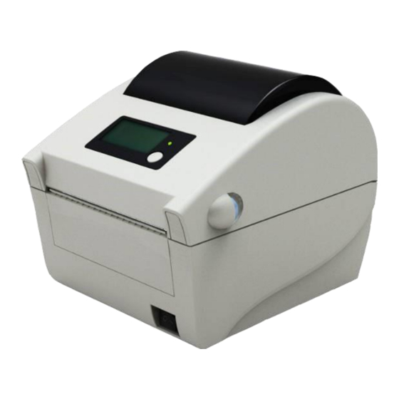
User’s Guide 1 Product description 1.1 Introduction Fastmark Z5 label printer is an ideal label and barcode printing device for office use, with delicate appearance and excellent performance. It can apply to many fields, such as real-time label printing, product label batch printing, transportation and logistics label printing, medical label printing and business label printing. -
Page 7: Appearance And Module
User’s Guide 1.3 Appearance and module window top cover LCD (optional) Logo plate bottom cover guard board for bottom cover button power switch cover open lever 10 LED 11 tear-off bar 12 print head fixing plate 13 print head 14 latch 15 guard board for print head 16 transmissive sensor 17 upper path... -
Page 8: Printer Installation
User’s Guide 2 Printer installation 2.1 Installation position Flatly place the printer on the operation table, which must be waterproof, moistureproof and dustproof. The maximal tilted angle should not exceed ±15° during installation. 2.2 Label roll installation Pull the cover open lever towards the front of the printer and turn the top cover upward to open it (see figure 2.2-1);... -
Page 9: Power Adapter Connection
User’s Guide 2.3 Power adapter connection Ensure the printer is turned off; Connect one end of the AC power input cable to power adapter, and then insert the other end of the power adapter into the power adapter interface on the back of printer; Insert the other end of AC power input cable into the 220V power socket. - Page 10 User’s Guide Run “Setup.exe” in the driver package, and read the related software license agreement carefully. If you accept the items in the license agreement, please click “I accept the items in the software license agreement”, and then click “Next” button; Select printer type and model to be installed.
- Page 11 User’s Guide Select setup type, and click “Next”; The driver will select the current OS type automatically, and click “Next”; Set printer port. “LPT1” is set as the default print port, but users can select it according to actual needs. If it is a serial port driver, please select “BYCOMx”...
- Page 12 User’s Guide The following window will appear indicating the installation process is under way. The following window will appear indicating the installation process has been completed. End of procedure. - 7 -...
-
Page 13: Printer Operations
User’s Guide 3 Printer operations 3.1 LED, buzzer, feed button and LCD 3.1.1 LED functions LED name Status Explanation Always on Printer is idle or working. Work LED (green) Prompt that the menu or parameter selection becomes effective. Flash twice See 3.2.2 Daily operations for details. -
Page 14: Daily Operations
User’s Guide Printer status Idle status Green LED is always on. Display LOGO and printer model information. Working status Green LED is always on. Display LOGO and PRINTING..Pause status Orange LED is always on. Display LOGO and pausing. Configuration status Green LED is always on. -
Page 15: Printer Parameter Settings
User’s Guide 3.3 Printer parameter settings 3.3.1 Button menu settings When the printer is idle, enter the configuration status through long press of the button. The common parameters of printer can be set and saved under configuration status. Parameters can be configured by the cooperation of LCD and button. -
Page 16: Detailed Parameter Setting Range
User’s Guide 1.BAUDRATE 115200 Figure 3.3.1-4 submenu of serial baud rate Repeat step 1-3 to change other parameters of the serial port. Save the modified parameters. Switch the menu to “SAVE ALL” option and press the button for a long time to save the modified parameters. -
Page 17: Sensor Position Adjustment
User’s Guide The printer feeds media and at the same time Calibration None rectifies the sensor parameters in order to adapt to the paper. 110, 300, 600, 1200, 2400, 4800, Baud rate 9600, 19200, 38400, 57600, 115200 Data bit (unit: bit) 7 bit, 8 bit Stop bit (unit: bit) 1 bit, 2 bit... -
Page 18: Print Position Adjustment
User’s Guide 3.5 Print position adjustment 1) Adjust vertical print position When the situation like figure A or B occurs, adjust the vertical print position to figure C. (For the detailed adjustment method, please refer to 3.3.1 Button menu settings). Figure 3.5-1 Caution: ... - Page 19 User’s Guide 3) Adjust tear-off position When the situation like figure G or H occurs, adjust the tear-off position to figure J. (For the detailed adjustment method, please refer to 3.3.2 Detailed parameter setting range). Figure 3.5-3 Caution: Figure G indicates that the tear-off position is upper than the correct position. Adjust it in negative direction;...
-
Page 20: Routine Maintenance
User’s Guide 4 Routine maintenance Clean the print head, platen roller and sensor every month according to the following steps. If the printer works in a tough environment, the maintenance times can be properly increased. 4.1 Cleaning print head When any of the following cases occurs, the print head should be cleaned: ... -
Page 21: Cleaning Platen Roller
User’s Guide 4.3 Cleaning platen roller When any of the following cases occurs, the platen roller should be cleaned: Printout is not clear; Feed and retract label/paper with noise; Something else sticks onto the platen roller. Follow the steps below to clean the platen roller: Turn off the printer and open the top cover;... -
Page 22: Troubleshooting
User’s Guide 5 Troubleshooting When the printer has a malfunction, please handle it with reference to this charter. If it still can not be cleared, please contact your local dealer. 5.1 Troubleshooting The error LED flashes and the buzzer beeps when an error or exceptional status occurs. At this time, the printer stops the printing. - Page 23 User’s Guide Troubleshooting methods: Error LED Reason analysis Solutions status Print head is lifted up. Please press down the print head. Print head up The micro switch has a Contact the maintainer. failure. Label roll is used up or Install a label/paper roll. no label roll is installed.
-
Page 24: Print Quality Problems
User’s Guide 5.2 Print quality problems Malfunction Reason Solution Print head or platen roller is dirty. Clean the print head or platen roller. Media does not meet the Use recommended media. requirement. Printout is unclear or has stains. Print darkness is too low. Increase print darkness. -
Page 25: Appendix
User’s Guide 6 Appendix Appendix 1 technical specification Appendix 1.1 main technical specifications Item Fastmark Z5 parameter 203DPI Resolution Print method Thermal 4.09” (104mm) Print width (Max.) 6 ips (152mm/s) Print speed (Max.) 32bit RISC microprocessor FLASH: 4MB SDRAM: 64MB Memory Extended FLASH: it can be extended to 8MB. - Page 26 User’s Guide Plain bitmaps in binary system, HEX, PCX, BMP and IMG files can Graphics be downloaded to FLASH or RAM. 1D Barcode: Code39, Code93, Codabar, Code128(Subsets A, B, and C), EAN- 13, EAN-8, UPC-A, UPC-E, UPC/EAN Extensions, Planet Code, Standard 2 of 5, Industrial 2 of 5, Interleaved 2 of 5, LOGMARS, Barcode GS1 DataBar (RSS)
-
Page 27: Appendix 1.2 Technical Specifications Of Media
User’s Guide Appendix 1.2 technical specifications of media Specifications of continuous media (unit: inches) Type Illustration Index Print width: 0.71”≤a≤ 4.72” Continuous without adhesive Base media width:0.71”≤a≤4.72” Print width: 0.71”≤b≤4.65” Continuous with adhesive Margin width: c ≤0.04” Table appendix 1.2-1 Discontinuous media specifications (unit: inches) Type Illustration... -
Page 28: Appendix 2.1 Printer Configuration Information
User’s Guide Appendix 2.1 printer configuration information Printer configuration information (BPLZ II) (this information is related to the configuration of the printer.) PRINTER CONFIGURATION: Z5 DT MODEL FV1.000 MAIN FIRMWARE DARKNESS TEAR OFF TEAR OFF PRINT MODE CONTINUOUS MEDIA TYPE MEDIA SENSOR TYPE MANUAL... -
Page 29: Appendix 3 Print And Paper Out Position
User’s Guide Appendix 3 print and paper out position Figure appendix 3-1 Caution: To take marked label/paper for example, the figure above explains the print and paper out position; Discontinuous label/paper locates by the front edge of the mark; ... -
Page 30: Appendix 4.2 Parallel Interface
User’s Guide Appendix 4.2 parallel interface Parallel interface works under IEEE1284 compatible mode. Definition Description Definition Description Input /STROBE Output SELECT Input Data0 Input /AutoFd Input Data1 Not defined Logic Input Data2 Ground Input Data3 Chassis Ground Input Data4 Input Data5 19 ~ 30 Signal Ground... -
Page 31: Appendix 5 Operation Guide For Label Loading Under Peel-Off Mode (Optional)
User’s Guide —— —— Reserve Input - Difference data signal input- —— —— Reserve —— —— Reserve power SPEED_LED power SPEED_LED output SPEED LED signal LINK_LED output LINK LED signal power LINK_LED power Table appendix 4.4-1 Ethernet signal list Appendix 5 operation guide for label loading under peel-off mode (optional) When using labels with adhesive, the user can refer to “2.4 Installing paper roll”...
Need help?
Do you have a question about the Fastmark Z5DT Series and is the answer not in the manual?
Questions and answers