Advertisement
Quick Links
DO NOT USE FOR ORAL SURGERY
Before operating the handpiece, carefully read and follow all of these instructions. Save these instructions for
future reference and observe all warnings and cautions.
INDICATIONS FOR USE
The Prophy Star
®
3 Handpiece is used by trained dental professionals to perform dental prophylaxis.
Caution: U.S. Federal law restricts this device to sale by or on the order of a licensed physician.
CONTENTS
SPECIFICATIONS
SPECIFICATIONS
Prophy Star 3 Handpiece, StarDental Part #264422
INSTALLATION & OPERATION
Diameter x Length:
DISPOSABLE PROPHY ANGLE
Operating Speed:
INSTALLATION
Power Output:
REMOVAL OF GRIP
Weight:
INSTALLATION OF GRIP
Operating Air Pressure:
Line Configuration:
SAFETY INSTRUCTIONS
Filtration:
REAR SEAL REPLACEMENT
Attachments:
CLEANING & STERILIZATION
TROUBLESHOOTING
REPLACEMENT PART NO.'S
135°C
Sterilizable up to 135°C
WARRANTY
INSTALLATION & OPERATION
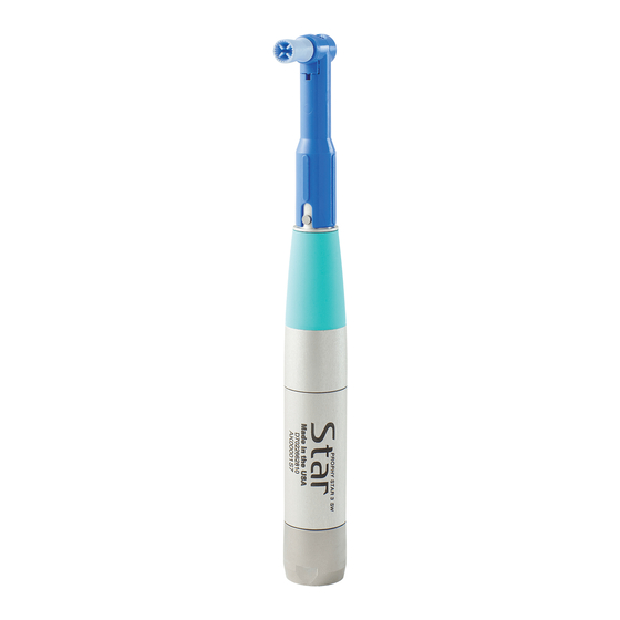
Materials Provided: Prophy Star 3 Handpiece(FIG.1), Cleaning Brush, Instructions
NOTE: Before installing the Prophy Star 3 Handpiece, be sure the air filter operates efficiently. Verify recommended
air filtration of 25 microns. Recommended air pressure, while operating, is 35 to 40 psi, see #2.
PROPHY STAR 3
BACK END
LOW SPEED HANDPIECE
StarDental®
Instruments
U.S.A.
NOTICE
If delivery unit has oil/mist lubrication, detach and drain; handpiece is LubeFree.
The Prophy Star 3 Handpiece (5,000 rpm) is suitable for low speed prophy procedures using disposable prophy
angles. The overall reduction in length of the Prophy Star 3 improves work positioning and reduces operator fatigue.
INSTALLATION & OPERATION, CONT.
1.
Verify that the back end of the handpiece corresponds to the delivery system's tubing configuration (ISO standard
4-line configuration FIG.2).
2.
Mount 4/6-line air pressure gauge, between the back end of handpiece and air supply tubing and obtain a
reading. Adjust air pressure until gauge reads 35-40 psi (FIG. 3) while operating handpiece with foot control
completely depressed.
NOTE: Operating pressure must be maintained between 35 psi and 40 psi.
NOTE: If a gauge is not available, set pressure at delivery head allowing 1 psi pressure loss for every foot of
tubing. For example, to operate at 35 psi and you are using either 5 feet or 12 feet of tubing, then the
pressure should be set at the delivery head to compensate for the air pressure losses:
5 feet of tubing
12 feet of tubing
3.
After adjustment, uncouple the pressure gauge and install handpiece as follows.
4.
Grasp the handpiece at the back end, in front of the threads between the thumb and finger as shown in FIG. 4.
.660in x 4.291in (16.76mm x 108.99mm)
0 to 5000 rpm
5.8 watts
5.
Slide tubing coupler until the end of the ISO tubing connector is exposed; hold in hand as shown with fingers
62 grams
securing the tubing.
35-40 psi (2.46 to 2.81 kgs/cm
)
2
4-Line
6.
Align and insert fittings on handpiece into the ISO tubing connector holes.
25 micron air filter recommended
7.
While applying slight pressure to hold fittings in the connector holes, slide coupler forward and engage threads.
Continue threading coupler clockwise until hand tight against the handpiece.
ISO standard Doriot style disposable
prophy angles
DISPOSABLE PROPHY ANGLE INSTALLATION
NOTE: Metal prophy angles are not recommended to be used with the Prophy Star handpiece. Prophy angles
with plastic stems with ISO standard Doriot couplings may be used. Attachments other than prophy angles are
not recommended with this handpiece.
1.
Insert the stem of the prophy angle into the chuck of the handpiece while making sure that the slot is aligned
with the nose pin.
2.
Push the angle until the slot is fully seated around the nose pin (FIG. 5).
FIG. 1
FIG. 2
DRIVE AIR
EXHAUST AIR
4/6 LINE PRESSURE GAUGE
FIG. 3
35 psi + 5 psi = 40 psi
35 psi + 12 psi = 47 psi
4 LINE TUBING ISO CONNECTOR
SWIVEL TUBES
TUBING COUPLER
Instruments
StarDental®
U.S.A.
THREADS
FIG. 4
TUBING
STEM
FIG. 5
CHUCK
SLOT
NOSE
PIN
NOTE: To remove the angle, simply pull the angle out of the handpiece.
REMOVAL OF GRIP
Rear of grip
1.
With thumb at rear of grip, push down and forward.
2. Continue pushing until grip clears nosepiece(FIG.6).
NOTE: Do Not Pull or Peel To Remove.
FIG. 6
INSTALLATION OF GRIP
Rear recess wall
1.
Push grip onto nosepiece at front of grip.
Front recess wall
2. Continue pushing until grip fits in nosepiece grip recess. Grip
should rest against front and rear recess wall.
Grip recess
Front of grip
FIG. 7
SAFETY INSTRUCTIONS
WARNING
TO MINIMIZE RISK OF SERIOUS INJURY:
• Always pull lightly on angle after mounting to handpiece to confirm that the angle is secured.
CAUTION
TO MINIMIZE RISK OF INJURY OR DAMAGE TO HANDPIECE OR ANGLE:
• Before use, verify concentric rotation by operating the handpiece outside the oral cavity in a
safe place. Do not use angles that do not run concentrically or produce excessive noise.
• Never operate handpiece without an angle installed.
• Use only recommended angles to prevent damage to chuck. An improperly inserted angle may
dislodge during use, causing injury to you or your patient.
REAR SEAL REPLACEMENT
StarDental®
Instruments
U.S.A.
REAR SEAL
Seals wear with repeated use. Once a year, or as needed, replace the rear seal (see FIG.8) with
StarDental Part #202897.
FIG. 8
Advertisement

Related Manuals for DentalEZ StarDental PROPHY STAR 3


Summary of Contents for DentalEZ StarDental PROPHY STAR 3
- Page 1 REMOVAL OF GRIP INSTALLATION & OPERATION, CONT. Verify that the back end of the handpiece corresponds to the delivery system’s tubing configuration (ISO standard Rear of grip 4-line configuration FIG.2). With thumb at rear of grip, push down and forward. FIG.
- Page 2 CLEANING: disassembly is required. Anyone wishing to return any DENTALEZ Inc. product to a DENTALEZ facility MUST obtain the proper RETURN AUTHORIZATION PROBLEM: PROPHY ANGLE SLIPS IN CHUCK NUMBER from the Customer Service Department. The RA Number must appear clearly marked on both the outside and inside of CLEANING - AUTOMATED: Washer-disinfectors are not recommended.
Need help?
Do you have a question about the StarDental PROPHY STAR 3 and is the answer not in the manual?
Questions and answers