Table of Contents
Advertisement
Quick Links
Advertisement
Table of Contents

Subscribe to Our Youtube Channel
Related Manuals for Intellisystem IT-ES5028-IM-4GS Series


Summary of Contents for Intellisystem IT-ES5028-IM-4GS Series
- Page 1 IT-ES5028-IM-4GS Series Managed Industrial Ethernet Switch User Manual...
-
Page 2: Packing List
Ethernet connection. The IT-ES5028-IM-4GS series switches have an operating temperature range of -40 to 75°C, and are designed with low consumption and without fan. The rugged hardware design makes the IT-ES5028-IM-4GS perfect for ensuring that your Ethernet equipment can withstand the rigors of industrial applications. -
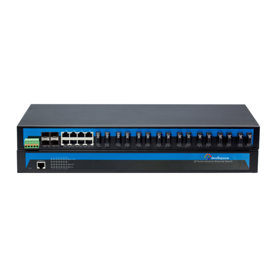
Page 3: Panel Layout
Support rate control, Broadcast storm control. Support 1 channel relay alarm output. Reliable Industrial grade design Industrial grade 4 design, -40-75℃ work temperature No fan design IP30 protection grade 19 inch rack mounting 【Panel layout】 IT-ES5028-IM-4GS-P (100/240VAC) Front panel Rear panel Restore factory settings. - Page 4 IT-ES5028-IM-4GS-2F-P (100/240VAC) Front panel Rear panel Restore factory settings. Console port. Link/ACT LEDs. Systems running LED. The power LED. Relay alarm LED. Hanger. Power input and Relay output terminal block. 1000Base-FX SFP port. 10/100BaseT(X) (RJ45) ports. 100Base-FX ports. Rear panel connector LEDs. IT-ES5028-IM-4GS-4F-P (100/240VAC) Front panel Rear panel...
- Page 5 Hanger. Power input and Relay output terminal block. 1000Base-FX SFP port. 10/100BaseT(X) (RJ45) ports. 100Base-FX ports. Rear panel connector LEDs. IT-ES5028-IM-4GS-8F-P (100/240VAC) Front panel Rear panel Restore factory settings. Console port. Link/ACT LEDs. Systems running LED. The power LED. Relay alarm LED. Hanger.
- Page 6 IT-ES5028-IM-4GS-12F-P (100/240VAC) Front panel Rear panel Restore factory settings. Console port. Link/ACT LEDs. Systems running LED. The power LED. Relay alarm LED. Hanger. Power input and Relay output terminal block. 1000Base-FX SFP port. 10/100BaseT(X) (RJ45) ports. 100Base-FX ports. Rear panel connector LEDs. IT-ES5028-IM-4GS-16F-P (100/240VAC) Front panel Rear panel...
- Page 7 Relay alarm LED. Hanger. Power input and Relay output terminal block. 1000Base-FX SFP port. 10/100BaseT(X) (RJ45) ports. 100Base-FX ports. Rear panel connector LEDs. IT-ES5028-IM-4GS-20F-P (100/240VAC) Front panel Rear panel 1. Restore factory settings. 2. Console port. 3. Link/ACT LEDs. 4. Systems running LED. 5.
-
Page 8: Power Supply Input
IT-ES5028-IM-4GS-24F-P (100/240VAC) Front panel Rear panel 1. Restore factory settings. 2. Console port. 3. Link/ACT LEDs. 4. Systems running LED. 5. Relay alarm LED. 6. The power LED. 7. Power input and Relay output terminal block. 8. 1000Base-FX SFP port. 9. -
Page 9: Console Port
【Console port】 This series product provided 1pcs procedure test port based in serial port. It adopts RJ45 interface, located in top panel, can configure the CLI command through RJ45 to DB9 female cable. 【Appearance and dimensions】 This series of dimensions length width height, between product series port number is different. Unit(mm)... -
Page 10: Relay Connection
【Relay connection】 Relay access terminals in the rear panel of the device, next to the power input parts, R+ and R - are in the middle of the relay alarm output section. It is used to detect both power failure and port failure. The open circuit state in normal non alarm state, when there is any alarm information to the closed state. - Page 11 MDI-X (Cross-over cable) MDI/MDI-X auto connection makes switch easy to use for customers without considering the type of network cable. 100Base-FX Fiber port 100Base-FX full-duplex SM or MM port, SC/ST/FC type .The fiber port must be used in pair, TX (transmit) port connect remote switch’s RX (receive) port;...
-
Page 12: Led Indicators
【LED Indicators】 LED indicator light on the front panel of product, the function of each LED is described in the table as below. System Indication LED State Description Power is being supplied to power input PWR input Power is not being supplied to power input PWR input ON/OFF System is not running well... -
Page 13: Specifications
4. All the cable cannot have break-down and terminal in the middle; 5. Cables should be straight in the hallways and turning; 6. Cable should be straight in the groove, and cannot beyond the groove in case of holding back the inlet and outlet holes. Cables should be banded and fixed when they are out of the groove;... - Page 14 Transfer distance: Twisted cable: 100M( standard CAT5/CAT5e cable) Multi-mode: 1310nm, 2/5Km Single-mode: 1310nm, 20/40/60Km 1550nm, 80/100/120Km LED indicators: Run indicator: Run Interface indicator: Link (1~24/G1~G4) Power supply indicator: PWR Alarm indicator: Alarm Power supply Input voltage: 100~240VAC Type of input:3 bit terminal block Overload Current Protection:1.2A Consumption IT-ES5028-IM-4GS-P (100/240VDC):...
- Page 15 IT-ES5028-IM-4GS-24F-P (100/240VAC): Unload consumption: 22.0W Full load consumption: 26.2W Working environment: Working temperature: -40~75℃ Storage temperature:-40~85℃ Relative Humidity: 5%~95% (no condensation) Mechanical Structure: Shell: IP30 protect grade, metal shell Installation: 19” 1U rack Size(W×H×D): 441.6mm×45mm×208.9mm Industry Standards: EMI:FCC Part 15, CISPR (EN55022) class A EMS EN61000-4-2 (ESD), Level 4 EN61000-4-3 (RS), Level 3 EN61000-4-4 (EFT), Level 4...
Need help?
Do you have a question about the IT-ES5028-IM-4GS Series and is the answer not in the manual?
Questions and answers