Table of Contents
Advertisement
Quick Links
Advertisement
Table of Contents

Subscribe to Our Youtube Channel
Related Manuals for Intellisystem IT-ES1024-IU Series


Summary of Contents for Intellisystem IT-ES1024-IU Series
- Page 1 IT-ES1024-IU series Industrial Ethernet switch User manual...
- Page 2 20 Fiber ports. The IT-ES1024-IU-24F consists of 24 Fiber ports that provide an economical solution for your industrial Ethernet connection. The IT-ES1024-IU series switches have an operating temperature range of -40 to 75°C, and are designed with low consumption and without fan. The rugged hardware des ign...
-
Page 3: Packing List
【Packing list】 Please check the packaging and accessories by your first using. Industrial Ethernet switch ⅹ 1 User manual ⅹ 1 Certificate of quality ⅹ 1 Warranty card ⅹ 1 Power adapter ⅹ 1 Please inform us or our distributor if your equipment have been damaged or lost any accessories, we will try our best to satisfy you. -
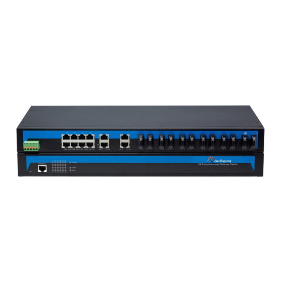
Page 4: Panel Layout
【Panel layout】 IT-ES1024-IU-P (100/240VAC) Front panel Rear panel Restore factory settings. Console port. Link/ACT LED. Systems running LED. The power LED. Relay alarm LED. Hangers. Power input and Relay output terminal block. 10/100BaseT(X) (RJ45) ports. Rear panel connector LED. IT-ES1024-IU-2F-P (100/240VAC) Front panel... - Page 5 Rear panel Restore factory settings. Console port. Link/ACT LED. Systems running LED. The power LED. Relay alarm LED. Hangers. Power input and Relay output terminal block. 10/100BaseT(X) (RJ45) ports. 100Base-FX ports. Rear panel connector LED. IT-ES1024-IU-4F-P (100/240VAC) Front panel Rear panel Restore factory settings.
- Page 6 Link/ACT LED. Systems running LED. The power LED. Relay alarm LED. Hangers. Power input and Relay output terminal block. 10/100BaseT(X) (RJ45) ports 100Base-FX ports Rear panel connector LED IT-ES1024-IU-8F-P (100/240VAC) Front panel Rear panel Restore factory settings Console port Link/ACT LED Systems running LED The power LED Relay alarm LED...
- Page 7 Rear panel connector LED IT-ES1024-IU-12F-P (100/240VAC) Front panel Rear panel Restore factory settings. Console port. Link/ACT LED. Systems running LED. The power LED. Relay alarm LED. Hangers. Power input and Relay output terminal block. 10/100BaseT(X) (RJ45) ports. 100Base-FX ports. Rear panel connector LED. IT-ES1024-IU-16F-P (100/240VAC) Front panel...
- Page 8 Rear panel Restore factory settings. Console port. Link/ACT LED. Systems running LED. The power LED. Relay alarm LED. Hangers. Power input and Relay output terminal block. 10/100BaseT(X) (RJ45) ports. 100Base-FX ports. Rear panel connector LED. IT-ES1024-IU-20F-P (100/240VAC) Front panel Rear panel 1.
- Page 9 5. Relay alarm LED. 6. The power LED. 7. Power input and Relay output terminal block. 8. 10/100BaseT(X) (RJ45) ports. 9. 100Base-FX ports. 10. Rear panel connector LED. IT-ES1024-IU-24F-P (100/240VAC) Front panel Rear panel 1. Restore factory settings. 2. Console port. 3.
-
Page 10: Appearance And Dimensions
【Appearance and dimensions】 This series of dimensions length width height, between product series port number is different. Unit(mm)... -
Page 11: Power Supply Input
【Power supply input】 The IT-ES1024-IU series Ethernet switch have singe power and redundancy power two kinds of power input. The singe power series rear panel provides 5 bit wiring terminal for AC100~240V power entered (L/+, GND, N/-) and relay output (R+, R-).The unmanaged Ethernet switch relay alarm function is invalid. -
Page 12: Communication Connector
【Communication connector】 10/100BaseT(X) Ethernet port The pin out of RJ45 port display as below, connect by UTP or STP. The connect distance is no more than 100m. 100Mbps is used 120Ω of UTP 5; 10Mbps is used 120Ω of UTP 3, 4, 5. RJ 45 port support automatic MDI/MDI-X operation. - Page 13 MDI (straight-through cable) MDI-X (Cross-over cable) MDI/MDI-X auto connection makes switch easy to use for customers without considering the type of network cable. 100Base-FX Fiber port 100Base-FX full-duplex SM or MM port, SC/ST/FC type .The fiber port must be used in pair, TX (transmit) port connect remote switch’s RX (receive) port;...
-
Page 14: Led Indicator
【LED Indicator】 LED indicator light on the front panel of product, the function of each LED is described in the table as below. System Indication LED State Description Power is being supplied to power input PWR1 input PWR1 Power is not being supplied to power input PWR1 input Power is being supplied to power input PWR2 input... -
Page 15: Installation
【Installation】 Before installation, confirm that the work environment meet the installation require, including the power needs and abundant space. Whether it is close to the connection equipment and other equipment are prepared or not. 1. Avoid in the sunshine, keep away from the heat fountainhead or the area where in intense EMI. - Page 16 Wiring Requirements Cable laying need to meet the following requirements, 1. It is needed to check whether the type, quantity and specification of cable match the requirement before cable laying; 2. It is needed to check the cable is damaged or not, factory records and quality assurance booklet before cable laying;...
-
Page 17: Specifications
9. It should have corresponding simple signal at both sides of the cable for maintaining. 【Specifications】 Technology Standard: Support IEEE802.3, IEEE802.3u, IEEE 802.3x Flow control: IEEE802.3x flow control, back press flow control Exchange attributes 100M forward speed: 148810pps Transmit mode: store and forward System exchange bandwidth: 12.8G MAC address table: 8K Memory: 4M... - Page 18 LED indicators Run indicator: Run Interface indicator: Link (1~24) Power supply indicator: PWR1 (PWR2) Power supply Input voltage: 100~240VAC Type of input: 3 bit terminal block Overload Current Protection: 1.2A Consumption IT-ES1024-IU-P (100/240VDC): Unload consumption: 6.9W Full load consumption: 9.4W ...
- Page 19 IT-ES1024-IU-20F-P (100/240VDC): Unload consumption: 18.8W Full load consumption: 20.7W IT-ES1024-IU-24F-P (100/240VAC): Unload consumption: 21.7W Full load consumption: 22.9W Working environment Working temperature: -40~75℃ Storage temperature:-40~85℃ Relative Humidity: 5%~95% (no condensation) Mechanical Structure Shell: IP30 protect grade, metal shell Installation: 19”...
- Page 20 Certification CE, FCC, RoHS, UL508 (Pending) Warranty: 5 years...
Need help?
Do you have a question about the IT-ES1024-IU Series and is the answer not in the manual?
Questions and answers