Table of Contents
Advertisement
Quick Links
Advertisement
Chapters
Table of Contents

Subscribe to Our Youtube Channel
Related Manuals for Nidek Medical Magellan Mapper


Summary of Contents for Nidek Medical Magellan Mapper
- Page 1 Magellan Mapper SERVICE MANUAL rev2.4...
- Page 2 Nidek Technologies. All rights are reserved. No part of this document may be reproduced in any manner without the express written permission of Nidek Technologies. Manual information NAME: Magellan Mapper Service Manual rev2.4 REVISION: DATE: May 10, 2011 REFERENCE: HW 22.0...
-
Page 3: Table Of Contents
NIDEK TECHNOLOGIES Table of contents Introduction ....................4 Cautions ...................... 5 Before service ..................5 During service ..................5 Removal and replacement procedures............8 Removing the left head cover .............. 9 Removing the right head cover ............10 Replacing the head covers ..............11 Removing the front ring .............. -
Page 4: Introduction
1 Introduction This service manual provides information for after-sales service of the Magellan Mapper. Only a trained technician can replace any parts of Magellan Mapper. For proper after-sale repair, it is necessary to understand this manual thoroughly before servicing. Refer to the Magellan Mapper Operator’s manual together with this manual. -
Page 5: Cautions
NIDEK TECHNOLOGIES 2 Cautions 2.1 Before service Only service personnel, who are used to handling tools and are familiar with instrument, can perform the servicing. Perform the servicing according to the procedures described in this manual. Before maintenance be sure to turn off the power switch and unplug the power cord. -
Page 6: Figure 1 Location A
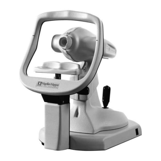
NIDEK TECHNOLOGIES Location Figure 1 Location A Figure 2 Location B MMSMEN2.4 – MM Service Manual rev.2.4 110329 Page 6 of 64... -
Page 7: Figure 3 Location C
NIDEK TECHNOLOGIES Figure 3 Location C Location table LA1: Chinrest LA2: Optical Head LA3: Joystick LA4: Power led LA5: Power Switch LB1: Left head cover LB2: Right head cover LB3: Chinrest base cover LC1: USB connector LC2: Fuses LC3: Power inlet LC4: S/N label MMSMEN2.4 –... -
Page 8: Removal And Replacement Procedures
NIDEK TECHNOLOGIES 3 Removal and replacement procedures Retain removed parts for the replacement procedures. Take note of wiring and connectors of the removed part. Reconnect in the same way the removed part. Turn upside down the equipment only when indicated by the procedure. Disconnect the signal cables, the power cables and the ground connections, from the parts to be removed. -
Page 9: Removing The Left Head Cover
NIDEK TECHNOLOGIES 3.1 Removing the left head cover Remove the two screws (see Figure 4). Figure 4 the left head cover screws. Remove the left head cover (see Figure 5). Figure 5 the left head cover. MMSMEN2.4 – MM Service Manual rev.2.4 110329 Page 9 of 64... -
Page 10: Removing The Right Head Cover
NIDEK TECHNOLOGIES 3.2 Removing the right head cover Remove the two screws (see Figure 6) Figure 6 the right head cover screws. Remove the right head cover (see Figure 7). Figure 7 the right head cover. MMSMEN2.4 – MM Service Manual rev.2.4 110329 Page 10 of 64... -
Page 11: Replacing The Head Covers
NIDEK TECHNOLOGIES 3.3 Replacing the head covers To replace the two head covers, insert the two retainers of the optical head (see Figure 8) into each head cover dedicated slot (see Figure 9). Figure 8 the head cover retainers. Figure 9 the cover retainer insertion slot. MMSMEN2.4 –... -
Page 12: Removing The Front Ring
NIDEK TECHNOLOGIES 3.4 Removing the front ring Before proceeding, remove the left and right head covers (see procedures no. 4.1, and 4.2). The front ring is jointed (see Figure 10). Figure 10 the Front ring. MMSMEN2.4 – MM Service Manual rev.2.4 110329 Page 12 of 64... -
Page 13: Removing The Head Cover Support Bracket
NIDEK TECHNOLOGIES 3.5 Removing the head cover support bracket. Before proceeding, perform the procedures no. 4.1, 4.2. 4.4. The support bracket is divided in two parts: A, B (see Figure 11). Figure 11 the head cover support bracket. Remove the four screws and the four nuts (see Figure 12). Figure 12 the four screws of support bracket. -
Page 14: Removing The Optical Head Assembly
NIDEK TECHNOLOGIES 3.6 Removing the optical head assembly Before proceeding, perform the procedures no. 4.1, 4.2, 4.4, 4.5. Unscrew the screw S. Pay attention at the connectors C. (See Figure 13) Figure 13 the Optical head before removing. MMSMEN2.4 – MM Service Manual rev.2.4 110329 Page 14 of 64... -
Page 15: Figure 14 The Optical Head Assembly
NIDEK TECHNOLOGIES Remove the optical head assembly H (see Figure 14). Figure 14 the optical head assembly. MMSMEN2.4 – MM Service Manual rev.2.4 110329 Page 15 of 64... -
Page 16: Figure 15 The S Screw: It Holds The Head
NIDEK TECHNOLOGIES When you unscrewing the screw S, avoid the screw falls inside the equipment (see Figure 15). Please remove it. Figure 15 the S screw: it holds the head. MMSMEN2.4 – MM Service Manual rev.2.4 110329 Page 16 of 64... -
Page 17: The Optical Head Assembly Replacement
NIDEK TECHNOLOGIES 3.7 The optical head assembly replacement When you replace the optical head, pay attention at the connection of electrical contacts (see Figure 16). A= optical head contacts. B= equipment contacts on the base. Figure 16 How to insert the connectors. MMSMEN2.4 –... -
Page 18: Removing The Moving Base Cover
NIDEK TECHNOLOGIES 3.8 Removing the moving base cover Before proceeding, perform the procedures no. 4.1, 4.2, 4.4, 4.5, 4,6. Figure 17 the moving base cover installed. Loosen the setscrew S, and remove the knob K (see Figure 18). Figure 18 the knob of moving cover. MMSMEN2.4 –... -
Page 19: Figure 19 The Nuts And Screw Of Moving Cover
NIDEK TECHNOLOGIES Remove the two nuts N, and the screw T (see Figure 19). The nuts are held to the cover with two grommets G. Figure 19 the nuts and screw of moving cover. Remove the moving base cover (see Figure 20). Figure 20 the moving base cover. -
Page 20: Removing The Chinrest
NIDEK TECHNOLOGIES 3.9 Removing the chinrest Unscrew the two screws of the base cover of the chinrest (see Figure 21). Figure 21 the two screws of chinrest base cover. Remove the base cover of chinrest (see Figure 22). Figure 22 the chinrest base cover. MMSMEN2.4 –... -
Page 21: Removing The Joystick
NIDEK TECHNOLOGIES 3.10 Removing the joystick Before proceeding, perform the procedures no. 4.1, 4.2, 4.4, 4.5, 4.6, and 4.8. Unscrew the four screws S1, S2, S3, and S4 and remove the belt stretcher BT (see Figure 23). Figure 23 the four screws and belt stretcher. MMSMEN2.4 –... -
Page 22: Figure 24 The Joystick
NIDEK TECHNOLOGIES Before to remove the joystick, remove the plug P (see Figure 25) from the jack (see Figure 24). Figure 24 the joystick. MMSMEN2.4 – MM Service Manual rev.2.4 110329 Page 22 of 64... -
Page 23: Figure 25 The Joystick Plug And Belt
NIDEK TECHNOLOGIES Pay attention when you remove the belt B, do not force and damage it. ( see Figure 25). Figure 25 the joystick plug and belt. MMSMEN2.4 – MM Service Manual rev.2.4 110329 Page 23 of 64... -
Page 24: Removing The Base Plastic Cover
NIDEK TECHNOLOGIES 3.11 Removing the base plastic cover If you have not already done, perform the procedures no. 4.1, 4.2, 4.4, 4.5, 4.6, 4.8, and 4.10. Unscrew the five screws (see Figure 26). Figure 26 the five screws of plastic base cover. MMSMEN2.4 –... -
Page 25: Figure 27 The Plastic Base Cover
NIDEK TECHNOLOGIES Remove the plastic base cover (see Figure 27). Figure 27 the plastic base cover. MMSMEN2.4 – MM Service Manual rev.2.4 110329 Page 25 of 64... -
Page 26: Removing The Base Metallic Cover
NIDEK TECHNOLOGIES 3.12 Removing the base metallic cover Before proceeding, perform the procedures no. 4.1, 4.2, 4.4, 4.5, 4.6, 4.8, 4.10, and 4.12. Unscrew the twelve screws (see Figure 28). Figure 28 the twelve screws of metallic base cover. MMSMEN2.4 – MM Service Manual rev.2.4 110329 Page 26 of 64... -
Page 27: Figure 29 The Metallic Base Cover
NIDEK TECHNOLOGIES Remove the metallic base cover (see Figure 29). Figure 29 the metallic base cover. MMSMEN2.4 – MM Service Manual rev.2.4 110329 Page 27 of 64... -
Page 28: Removing Cable Plate Mm2-Me126
NIDEK TECHNOLOGIES 3.13 Removing cable plate MM2-ME126 Before proceeding, perform the procedures no. 4.1, 4.2, 4.4, 4.5, 4.6, 4.8, 4.10, and 4.12. Unscrew the two screws (see Figure 30). Figure 30 View of the base MMSMEN2.4 – MM Service Manual rev.2.4 110329 Page 28 of 64... -
Page 29: Removing Chinrest Cable Mm2-Wi003
NIDEK TECHNOLOGIES 3.14 Removing chinrest cable MM2-WI003 Unscrew one screw and remove the plug (see Figure 31). Figure 31 Chinrest support Unscrew the five screws (see Figure 32 Figure 32 Chinrest mechanism MMSMEN2.4 – MM Service Manual rev.2.4 110329 Page 29 of 64... -
Page 30: Figure 33 Mm2-Wi003 Cable
NIDEK TECHNOLOGIES Cut the cable MM2-WI003 near the plug and remove the cable from the chinrest (see Figure 33) Figure 33 MM2-WI003 cable MMSMEN2.4 – MM Service Manual rev.2.4 110329 Page 30 of 64... -
Page 31: Insert The New Chinrest Cable Mm2-Wi019
NIDEK TECHNOLOGIES 3.15 Insert the new chinrest cable MM2-WI019 -Move to the lower position the chinrest (see Figure 34) -Insert the cable in to the hole (see Figure 34) Figure 34 chinrest and MM2 WI019 cable Figure 35 Positions the micro switch like the Figure 35 MMSMEN2.4 –... -
Page 32: Figure 36 Position Of Micro Switch
NIDEK TECHNOLOGIES Pay attention to the color cable (see Figure 36), screw the four screw (See Figure 36) YELLOW/ GREEN CABLES WHITE/ BROWN CABLES Figure 36 Position of micro switch Place the shield of the cable in the central position and screw the central screw (central screw: screw M3X6 + spring lock washer + plain washer) (see Figure Figure 37 Chinrest MMSMEN2.4 –... -
Page 33: Setup Of Micro Switch And Pin Mm2_Wi019 Cable
NIDEK TECHNOLOGIES 3.16 Setup of micro switch and pin MM2_WI019 cable SCREWS Figure 38 down position of micro switch Set of micro switch Unscrew the two screws and set the position of micro switch, after, screw the two screws (see Figure 38). Bottom position: When the micro switch is active/on (click sound when you move down) L=0.8mm (see Figure 39) -
Page 34: Figure 40 Chinrest
NIDEK TECHNOLOGIES Central position: When the micro switch is inactive/OFF (click sound) when you move in the central position (see Figure 41) In the central position all micro switch is OFF (see Figure 41) DOWN POSITION UPPER POSITION MICROSWITCH ON MICROSWITCH OFF Figure 40 Chinrest CENTRAL POSITION... -
Page 35: Figure 42 Upper Position Of Micro Switch (Off)
NIDEK TECHNOLOGIES Figure 42 Upper position of micro switch (OFF) Pin of MM2-WI019 (see Figure 42) Figure 43 CN1 of MM2-WI019 Insert the pin in the Amp MODU housing (see Figure 44) Figure 44 Connector CN1 of MM2-WI019 MMSMEN2.4 – MM Service Manual rev.2.4 110329 Page 35 of 64... -
Page 36: Removing The Plug Of Chinrest Cable Mm2-Wi010
NIDEK TECHNOLOGIES 3.17 Removing the plug of chinrest cable MM2-WI010 Unscrew the ring of plug (see Figure 45) Remove the tie mount cable TIE MOUNT CABLE Figure 45 MMSMEN2.4 – MM Service Manual rev.2.4 110329 Page 36 of 64... -
Page 37: Assembly Front Cable Support Mm2-Me201
NIDEK TECHNOLOGIES 3.18 Assembly front cable support MM2-ME201 Unscrew the screw M5X16 show in the Figure 46 MM2-ME201 Figure 46 MM2-ME201 and screw SCREW REMOVED Figure 47 MM2-ME201 and screw Assembly the cable support with M5X10 screw, lock washers and plain washer (see Figure 47 and Figure 48) SCREW REMOVED (M5 x16) -
Page 38: How Replace Mm2-Wi010 Cable With Mm2-Wi018 Cable
NIDEK TECHNOLOGIES 3.19 How replace MM2-WI010 cable with MM2-WI018 cable MM2-WI010 Figure 49 cable near the Head Remove MM2-WI010 cable (see Figure 50) Figure 50 MM2-WI010 removed MMSMEN2.4 – MM Service Manual rev.2.4 110329 Page 38 of 64... -
Page 39: Figure 51
NIDEK TECHNOLOGIES Insert MM2-WI018 cable (see Figure 51) MM2-WI018 Figure 51 Place the cable as in Figure 52 and Figure 53 and fix the shield with the screw Pay attention of the height of the cables (see Figure 53) MM2-WI002 MM2-WI018 MM2-WI008 MM2-WI004... -
Page 40: Figure 53
NIDEK TECHNOLOGIES Figure 53 Unscrew two screw “S” and remove MM2-WI010 (see Figure 54) MM2-WI018 MM2-WI010 Figure 54 MMSMEN2.4 – MM Service Manual rev.2.4 110329 Page 40 of 64... -
Page 41: Figure 55 Length Of Cable
NIDEK TECHNOLOGIES Pay attention of the length of the cables (see Figure 55 and Figure 56) L=120mm MM2-WI018 Figure 55 Length of cable Assembly the cable tie and lock MM2-WI002, MM2-WI004, MM2-WI008, MM2-WI018 (see Figure 55, Figure 56) Screw the screw show in the Figure 56 L=120mm CABLE TIE WITH SCREW... -
Page 42: Figure 57 Mm2-Wi002
NIDEK TECHNOLOGIES Pay attention of the length of MM2-WI002, L=165mm (see Figure 57) L=165mm Figure 57 MM2-WI002 Assembly the cable tie (see Figure 58) Pay attention: the cable must be nearest to the sheet in the point “1” (see Figure 58) CABLE TIE MM2_WI002 CABLE TIE... -
Page 43: Assembly Rear Support Cable Mm2-Me201
NIDEK TECHNOLOGIES 3.20 Assembly rear support cable MM2-ME201 WASHERS M5 X 10 SCREW MM2-ME201 Figure 59 MM2-ME201 and screw Assembly the cable support with M5X10 screw, lock washer and plain washer (see Figure 60) MM2-ME201 CHINREST SUPPORT Figure 60 Chinrest support with MM2-ME201 MMSMEN2.4 –... -
Page 44: Lock Chinrest Cable Mm2-Wi018 To Rear Support Cable
NIDEK TECHNOLOGIES 3.21 Lock chinrest cable MM2-WI018 to rear support cable L=190mm MM2-WI018 Figure 61 MM2-WI018 Pay attention of the length of cable MM2-WI018 (see Figure 61 and Figure 62) Fix the chinrest cable MM2-WI018 with cable tie (see Figure 63 and Figure 64) Pay attention of the position of the head of the cable tie (see Figure 64) MM2-WI018 L=190mm... -
Page 45: Figure 63 Fixing Cable Tie
NIDEK TECHNOLOGIES CABLE TIE Figure 63 Fixing cable tie HEAD OF THE CABLE Figure 64 Cable tie MMSMEN2.4 – MM Service Manual rev.2.4 110329 Page 45 of 64... -
Page 46: Figure 65 Mm2-Me018
NIDEK TECHNOLOGIES MM2-WI018 Figure 65 MM2-ME018 Assembly MM2_ME126 and screw the two screws (see Figure 66) MM2-ME126 Figure 66 MM2-ME126 MMSMEN2.4 – MM Service Manual rev.2.4 110329 Page 46 of 64... -
Page 47: Connect Two Chinrest Cable
NIDEK TECHNOLOGIES 3.22 Connect two chinrest cable MM2-WI019 MM2-WI018 Figure 67 MM2-WI018 and MM2-WI019 MM2-WI018: Insert the pin in the Amp MODU housing (see Figure 68) Figure 68 CN1 of MM2-WI018 MMSMEN2.4 – MM Service Manual rev.2.4 110329 Page 47 of 64... -
Page 48: Figure 69 Fixing Of Mm2-Wi018 And Mm2-Wi019
NIDEK TECHNOLOGIES Connect MM2-WI018 to MM2-WI019 (see Figure 69) Fix the connector to support cable with cable tie MM2-WI019 CABLE TIE MM2-WI018 Figure 69 Fixing of MM2-WI018 and MM2-WI019 Verify the movement up/down of chinrest and cable (see Figure 70 and Figure POSITION Figure 70 Up position of chinrest MMSMEN2.4 –... -
Page 49: Figure 71 Down Position Of Chinrest
NIDEK TECHNOLOGIES DOWN POSITION Figure 71 down position of chinrest MMSMEN2.4 – MM Service Manual rev.2.4 110329 Page 49 of 64... -
Page 50: New Ccd Camera Videology 21D389-Usb
NIDEK TECHNOLOGIES 4 New CCD Camera Videology 21D389-USB In the fig. below are showed the connection cables to the CCD camera 21D389-USB. The replacement of the camera can be performed only by Manufacturer Nidek Technologies S.r.l., as a dedicated calibration procedure is needed. -
Page 51: Hid & Hub Usb 2.0 Board
NIDEK TECHNOLOGIES 5 HID & hub USB 2.0 Board. View of the connection cable on the MAG-EL100 rev5 To change the board you only have to unscrew tree screws. Old version that must be replaced, the board EL103 (frame grabber) under the previous, must be removed. -
Page 52: Mag-El100 Rev5
NIDEK TECHNOLOGIES 6 MAG-EL100 rev5 The cable WI021 must be pass through the hole on the head sheet metal. MM2-WI021 Figure 74 MM2-WI021 MMSMEN2.4 – MM Service Manual rev.2.4 110329 Page 52 of 64... -
Page 53: Figure 75 Ground
NIDEK TECHNOLOGIES Then you must connect the cable MM2-WI021 to the MAG-EL102. Pay attention to connect the ground cable. Figure 75 Ground MMSMEN2.4 – MM Service Manual rev.2.4 110329 Page 53 of 64... -
Page 54: Replacement
Take the exam with calibration ball. Verify the accuracy of the exam. Exam test Take exams with Magellan Mapper and verify in Navis. Verify the accuracy of the exams. MMSMEN2.4 – MM Service Manual rev.2.4 110329 Page 54 of 64... -
Page 55: Wiring
NIDEK TECHNOLOGIES 8 Wiring 8.1 Cables List MM2-WI002 rev1 Joystick bottom cable MM2-WI004 rev2 USB bottom cable MM2-WI005 rev2 LASER and rings cable MM2-WI007 rev1 Target cable MM2-WI008 rev8 Power bottom cable MM2-WI018 rev0 Internal chinrest cable MM2-WI019 rev1 Bottom chinrest cable MM2-WI021 rev0 Head Board cable MM2-WI023 rev0... -
Page 56: Figure 76 Wd Wi002
NIDEK TECHNOLOGIES 8.3 WD 1 Figure 76 WD WI002 Figure 77 WD WI004 Figure 78 WD WI005 MMSMEN2.4 – MM Service Manual rev.2.4 110329 Page 56 of 64... -
Page 57: Figure 79 Wd Wi007
NIDEK TECHNOLOGIES Figure 79 WD WI007 Figure 80 WD WI008 Figure 81 WD WI018 Figure 82 WD WI019 MMSMEN2.4 – MM Service Manual rev.2.4 110329 Page 57 of 64... -
Page 58: Figure 83 Wi Wi021
NIDEK TECHNOLOGIES Figure 83 WI WI021 Figure 84 WI WI023 MMSMEN2.4 – MM Service Manual rev.2.4 110329 Page 58 of 64... -
Page 59: Figure 85 The Wd Complete Wiring Diagram
NIDEK TECHNOLOGIES Figure 85 The WD complete wiring diagram. MMSMEN2.4 – MM Service Manual rev.2.4 110329 Page 59 of 64... -
Page 60: Technical Specifications
NIDEK TECHNOLOGIES 9 Technical specifications Class and Type 1B (according to IEC 601-1) Power Supply From 100 to 240 VAC; 50 / 60 Hz Main switch Compliance with IEC 60417-5007 “ON” (power) and IEC 60417-5008 “OFF” (power) Detachable power supply cord –... -
Page 61: Tools
NIDEK TECHNOLOGIES 10 Tools 10.1 Special tools Some services may need this device: Verification ball. 10.2 Service tools set Phillips screwdriver: small and middle Flat blade screwdriver: small and middle Nippers Small pliers Tester ... -
Page 62: Parts And Assemblies List
NIDEK TECHNOLOGIES 11 Parts and assemblies list Attention. Not all of these parts and assemblies are on the field replaceable. ITEM PART NO. Verification Ball MM2-AP007 Controller board MAG-EL100 rev5 Head connector board MAG-EL102 rev2 USB connector MAG-EL104 rev2 Power supply assembly MM1-AP034 Keratoscope assembly MM2-AP006... - Page 63 NIDEK TECHNOLOGIES Table of Figure Figure 1 Location A ............................6 Figure 2 Location B ............................6 Figure 3 Location C ............................7 Figure 4 the left head cover screws......................9 Figure 5 the left head cover.......................... 9 Figure 6 the right head cover screws.
- Page 64 NIDEK TECHNOLOGIES Figure 55 Length of cable ........................... 41 Figure 56 Length of cable ........................... 41 Figure 57 MM2-WI002 ..........................42 Figure 58 Position Of cable ......................... 42 Figure 59 MM2-ME201 and screw ......................43 Figure 60 Chinrest support with MM2-ME201 ................... 43 Figure 61 MM2-WI018 ..........................
Need help?
Do you have a question about the Magellan Mapper and is the answer not in the manual?
Questions and answers