Sign In
Upload
Manuals
Brands
Nidek Medical Manuals
Medical Equipment
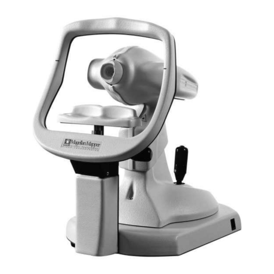
Magellan Mapper
User Manuals: Nidek Medical Magellan Mapper Device
Manuals and User Guides for Nidek Medical Magellan Mapper Device. We have
1
Nidek Medical Magellan Mapper Device manual available for free PDF download: Service Manual
Nidek Medical Magellan Mapper Service Manual (64 pages)
Brand:
Nidek Medical
| Category:
Medical Equipment
| Size: 3 MB
Table of Contents
Table of Contents
3
Introduction
4
Cautions
5
Before Service
5
During Service
5
Figure 1 Location a
6
Figure 2 Location B
6
Figure 3 Location C
7
Removal and Replacement Procedures
8
Removing the Left Head Cover
9
Figure 4 the Left Head Cover Screws
9
Figure 5 the Left Head Cover
9
Removing the Right Head Cover
10
Figure 6 the Right Head Cover Screws
10
Figure 7 the Right Head Cover
10
Figure 9 the Cover Retainer Insertion Slot
11
Replacing the Head Covers
11
Figure 8 the Head Cover Retainers
11
Removing the Front Ring
12
Figure 10 the Front Ring
12
Removing the Head Cover Support Bracket
13
Figure 11 the Head Cover Support Bracket
13
Figure 12 the Four Screws of Support Bracket
13
Removing the Optical Head Assembly
14
Figure 13 the Optical Head before Removing
14
Figure 14 the Optical Head Assembly
15
Figure 15 the S Screw: It Holds the Head
16
The Optical Head Assembly Replacement
17
Figure 16 How to Insert the Connectors
17
Figure 18 the Knob of Moving Cover
18
Figure 17 the Moving Base Cover Installed
18
Removing the Moving Base Cover
18
Figure 19 the Nuts and Screw of Moving Cover
19
Figure 20 the Moving Base Cover
19
Removing the Chinrest
20
Figure 21 the Two Screws of Chinrest Base Cover
20
Figure 22 the Chinrest Base Cover
20
Removing the Joystick
21
Figure 23 the Four Screws and Belt Stretcher
21
Figure 24 the Joystick
22
Figure 25 the Joystick Plug and Belt
23
Removing the Base Plastic Cover
24
Figure 26 the Five Screws of Plastic Base Cover
24
Figure 27 the Plastic Base Cover
25
Removing the Base Metallic Cover
26
Figure 28 the Twelve Screws of Metallic Base Cover
26
Figure 29 the Metallic Base Cover
27
Removing Cable Plate MM2-ME126
28
Figure 30 View of the Base
28
Removing Chinrest Cable MM2-WI003
29
Figure 31 Chinrest Support
29
Figure 32 Chinrest Mechanism
29
Figure 33 MM2-WI003 Cable
30
Insert the New Chinrest Cable MM2-WI019
31
Figure 34 Chinrest and MM2 WI019 Cable
31
Figure 35
31
Figure 36 Position of Micro Switch
32
Figure 37 Chinrest
32
Setup of Micro Switch and Pin MM2_WI019 Cable
33
Figure 38 down Position of Micro Switch
33
Figure 39
33
Figure 41 Central Position of Micro Switch
34
Figure 40 Chinrest
34
Figure 44 Connector CN1 of MM2-WI019
35
Figure 42 Upper Position of Micro Switch (OFF)
35
Figure 43 CN1 of MM2-WI019
35
Removing the Plug of Chinrest Cable MM2-WI010
36
Figure 45
36
Assembly Front Cable Support MM2-ME201
37
Figure 46 MM2-ME201 and Screw
37
Figure 47 MM2-ME201 and Screw
37
Figure 48 Chinrest Support
37
How Replace MM2-WI010 Cable with MM2-WI018 Cable
38
Figure 49 Cable Near the Head
38
Figure 50 MM2-WI010 Removed
38
Figure 51
39
Figure 52
39
Figure 54
40
Figure 53
40
Figure 56 Length of Cable
41
Figure 55 Length of Cable
41
Figure 57 MM2-WI002
42
Figure 58 Position of Cable
42
Assembly Rear Support Cable MM2-ME201
43
Figure 59 MM2-ME201 and Screw
43
Figure 60 Chinrest Support with MM2-ME201
43
Lock Chinrest Cable MM2-WI018 to Rear Support Cable
44
Figure 61 MM2-WI018
44
Figure 62 Fixing of MM2-ME018 Cable
44
Figure 63 Fixing Cable Tie
45
Figure 64 Cable Tie
45
Figure 65 MM2-ME018
46
Figure 66 MM2-ME126
46
Figure 68 CN1 of MM2-WI018
47
Connect Two Chinrest Cable
47
Figure 67 MM2-WI018 and MM2-WI019
47
Figure 70 up Position of Chinrest
48
Figure 69 Fixing of MM2-WI018 and MM2-WI019
48
Figure 71 down Position of Chinrest
49
New CCD Camera Videology 21D389-USB
50
Figure 72 CCD Camera
50
HID & Hub USB 2.0 Board
51
Figure 73 MAG-EL100 Rev5
51
MAG-EL100 Rev5
52
Figure 74 MM2-WI021
52
Figure 75 Ground
53
Replacement
54
Wiring
55
Cables List
55
Electronic Boards List
55
Figure 78 WD WI005
56
Figure 76 WD WI002
56
Figure 77 WD WI004
56
Figure 79 WD WI007
57
Figure 80 WD WI008
57
Figure 81 WD WI018
57
Figure 82 WD WI019
57
Figure 83 WI WI021
58
Figure 84 WI WI023
58
Figure 85 the WD Complete Wiring Diagram
59
Technical Specifications
60
Tools
61
Special Tools
61
Service Tools Set
61
Parts and Assemblies List
62
Nidek Technologies Table of Figure
63
Advertisement
Advertisement
Related Products
Nidek Medical Mark 5 Nuvo Lite Family
Nidek Medical Mark 5 Nuvo OCSI Lite 3
Nidek Medical Mark 5 Nuvo Lite Series
Nidek Medical Mark 5 Nuvo MB
Nidek Medical Mark 5 Nuvo 10
Nidek Medical Mark5 Nuvo
Nidek Medical Mark 5 Nuvo 8
Nidek Medical ME-1000
Nidek Medical MC-500
Nidek Medical MC-300
Nidek Medical Categories
Medical Equipment
Measuring Instruments
Edger
Oxygen Equipment
Laboratory Equipment
More Nidek Medical Manuals
Login
Sign In
OR
Sign in with Facebook
Sign in with Google
Upload manual
Upload from disk
Upload from URL