Table of Contents
Advertisement
Quick Links
§ 1
INTRODUCTION ........................................................................................................ 1-1
§ 2
SAFETY PRECAUTIONS ............................................................................................ 2-1
§ 3
TROUBLE SHOOTING ............................................................................................... 3-1
§ 4
SUB TOUBLE SHOOTING ......................................................................................... 4-1
4.1 Initialization screen does not appear on the CB display. ............................................... 4-1
4.1.1 Backlight of the LCD module does not light up. .................................................. 4-2
4.2 Initialization is not completed properly. ........................................................................ 4-3
4.2.1 The battery AS does not move to the right and left. ............................................ 4-4
4.2.2 The R disk AS does not turn. ............................................................................. 4-5
4.2.3 The L disk AS does not turn. ............................................................................. 4-7
4.2.4 The PD and convergence of the MB is not initialized properly. ............................ 4-9
4.2.5 The right disk of the MB is not initialized properly. ............................................ 4-10
4.2.6 The left disk of the MB is not initialized properly. .............................................. 4-11
4.3 An error message appears. ....................................................................................... 4-12
4.3.1 "Error 01: Communication Error CB-MB" appears. ......................................... 4-13
4.3.2 "Error 11: Communication Error CB-RB" appears. .......................................... 4-14
4.3.3 "No appointment data!!" appears. ................................................................... 4-14
4.3.4 "Chart doesn't work." appears. ....................................................................... 4-15
4.3.5 "Setup data is initialized." appears. ................................................................... 4-16
4.3.6 "CF card -- Read Error!!" appears. ................................................................ 4-16
4.3.7 "CF card -- Write Error!!" appears. ................................................................ 4-16
4.3.8 "CF card -- File Error!!" appears. ................................................................... 4-16
4.3.9 "CF card -- File not found!!" appears. ............................................................. 4-16
4.3.10 "CF card -- Card not found!!" appears. ........................................................ 4-16
4.3.11 "No data!!" appears. ..................................................................................... 4-16
4.4 The instrument cannot be operated with the control box. ............................................ 4-17
4.4.1 The instrument cannot be operated with the switches. ....................................... 4-17
4.4.2 The instrument cannot be operated by turning the dial. ...................................... 4-18
4.4.3 The instrument cannot be operated with the touch-screen panel. ....................... 4-18
4.5 The compact flash memory card cannot be used. ....................................................... 4-19
4.6 The IC card cannot be used. ..................................................................................... 4-19
4.7 The printer does not print. ......................................................................................... 4-20
4.9 The chart projector does not work as specified with the control box. ......................... 4-22
Table of Contents
MRT10*RDA001A/E
Page
Advertisement
Table of Contents

Related Manuals for Nidek Medical RT-5100


Summary of Contents for Nidek Medical RT-5100
-
Page 1: Table Of Contents
MRT10*RDA001A/E Table of Contents Page § 1 INTRODUCTION ......................1-1 § 2 SAFETY PRECAUTIONS .................... 2-1 § 3 TROUBLE SHOOTING ....................3-1 § 4 SUB TOUBLE SHOOTING ..................4-1 4.1 Initialization screen does not appear on the CB display..........4-1 4.1.1 Backlight of the LCD module does not light up. - Page 2 MRT10*RDA001A/E Page § 5 REMOVING COVERS ....................5-1 5.1 Covers of the main body ..................... 5-1 5.1.1 Face shields R and L ..................5-1 5.1.2 Rear covers ...................... 5-1 5.1.2.1 Rear cover R ..................5-1 5.1.2.2 Rear cover L ..................5-1 5.1.3 Front covers .....................
- Page 3 MRT10*RDA001A/E Page 6.9.1.1 CON sensor of the upper brace R ............6-7 6.9.1.2 CON sensor of the upper brace L ............6-7 6.9.2 PD sensors ....................... 6-8 6.9.2.1 PD sensor of the upper brace R ............. 6-8 6.9.2.2 PD sensor of the upper brace L ............. 6-8 6.10 Motors and sensors of frame R .................
- Page 4 MRT10*RDA001A/E 6.16 R motor driver board ....................6-20 6.17 MB main board ...................... 6-21 6.18 LCD AS ........................ 6-21 6.19 CB main board ....................... 6-22 6.20 Key I/F board ......................6-22 6.21 Link board ......................6-23 6.22 Rotary encoder ...................... 6-23 6.23 LCD I/F board .......................
-
Page 5: Introduction
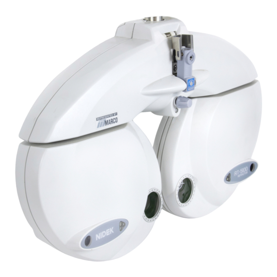
• This service manual provides information for after-sales service for the NIDEK refractor, model: RT-5100. • Refer to the RT-5100 Operator’s Manual and Parts List. • Specifications are subject to change without notice for improvement. Refer to the Technical Bulletins (T.B.) for important changes. - Page 6 MRT10*RDA001A/E 1 - 2...
-
Page 7: Safety Precautions
MRT10*RDA001A/E § 2 SAFETY PRECAUTIONS <General precautions> • Only the service persons who are accustomed to using tools, and have a deep knowledge of this instrument are allowed to repair the instrument. • Proceed right work in accordance with the procedure. If not, accidents or failure of the instrument may result. - Page 8 MRT10*RDA001A/E 2 - 2...
-
Page 9: Troubleshooting
MRT10*RDA001A/E § 3 TROUBLESHOOTING Turn ON the main switch. 4.1 The starting screen does not appear on the control Does the starting screen appear on the control box? box. Is the initialization completed properly? 4.2 Initialization is not completed properly. Does any error message appear? 4.3 An error message appears. - Page 10 MRT10*RDA001A/E 3 - 2...
-
Page 11: Sub Touble Shooting
MRT10*RDA001A/E § 4 SUB TROUBLESHOOTING 4.1 Initialization screen does not appear on the CB display. Is the power supply voltage within the specified range? Obtain the specified voltage. Does the fuse of the RB blow? Replace the fuse of the RB. Is the voltage setting of the RB correct? Set the correct voltage of the RB. -
Page 12: Backlight Of The Lcd Module Does Not Light Up
MRT10*RDA001A/E Is the voltage between 1-3 pins of connector J33 on the Replace the LCD I/F board (34085-BA13). (See 6.23.) LCD I/F board (34085-BA13) DC+3.3V? Replace the color LCD module (42203-E016). (See 6.25.) Is the symptom relieved? Replace the CB main board (34085-BA11). (See 6.19.) Completion 4.1.1 Backlight of the LCD module does not light up. -
Page 13: Initialization Is Not Completed Properly
MRT10*RDA001A/E 4.2 Initialization is not completed properly. Is the voltage between A1-A4 pins of connector J1 on the MB main board (34085-BA01) DC+5V, and the Check the wiring of cable MB and replace it. voltage between A12-A8 pins DC+16.5V? Does the battery AS (34085-1000) move to the right 4.2.1 The battery AS (34085-1000) does not move to and left? the right and left. -
Page 14: The Battery As Does Not Move To The Right And Left
MRT10*RDA001A/E 4.2.1 The battery AS does not move to the right and left. Does motor CON (34085-E013) of the PD motor R Replace the PD motor R (34085-2510). (See 6.7.1.) (34085-2510) break? Does motor CON (34085-E013) of the CON motor R Replace the CON motor R (34085-2520). -
Page 15: The R Disk As Does Not Turn
MRT10*RDA001A/E 4.2.2 The R disk AS does not turn. Is the voltage of connector J3 on the R motor CPU board (34085-BA04) as described below? Replace the MB main board (34085-BA01). (See 6.17.) A3-A1 pins :DC+5V A4-A1 pins :DC+16.5V Is the voltage of connector P1 on the R motor CPU board (34085-BA04) as described below? Replace the R motor CPU board (34085-BA04). - Page 16 MRT10*RDA001A/E Does motor PCA (34085-1320) for the CA disk R Replace motor PCA (34085-1320) for the CA disk R. break? (See 6.10.2.1.) Does motor PCA (34085-1320) for the P1 disk R Replace motor PCA (34085-1320) for the P1 disk R. break? (See 6.10.2.2.) Does motor PCA (34085-1320) for the P2 disk R...
-
Page 17: The L Disk As Does Not Turn
MRT10*RDA001A/E 4.2.3 The L disk AS does not turn. Is the voltage of connector J3 on the L motor CPU board (34085-BA02) as described below? Replace the MB main board (34085-BA01). (See 6.17.) A3-A1 pins :DC+5V A4-A1 pins :DC+16.5V Is the voltage of connector P1 on the L motor CPU board (34085-BA02) as described below? Replace the L motor CPU board (34085-BA02). - Page 18 MRT10*RDA001A/E Does motor PCA (34085-1320) for the CA disk L Replace motor PCA (34085-1320) for the CA disk L. break? (See 6.11.2.1.) Does motor PCA (34085-1320) for the PA disk L Replace motor PCA (34085-1320) for the P1 disk L. break? (See 6.11.2.2.) Does motor PCA (34085-1320) for the P2 disk L...
-
Page 19: The Pd And Convergence Of The Mb Is Not Initialized Properly
MRT10*RDA001A/E 4.2.4 The PD and convergence of the MB is not initialized properly. Turn OFF the main switch. Does the driving gear of Adjust the engagement of the PD gear that does not the step-out motor turn smoothly when turning it by turn smoothly. -
Page 20: The Right Disk Of The Mb Is Not Initialized Properly
MRT10*RDA001A/E 4.2.5 The right disk of the MB is not initialized properly. Turn OFF the main switch. Does the driving gear of Adjust the gear engagement of the disk, axis and such the step-out motor turn smoothly when turning it by that do not turn smoothly. -
Page 21: The Left Disk Of The Mb Is Not Initialized Properly
MRT10*RDA001A/E 4.2.6 The left disk of the MB is not initialized properly. Turn OFF the main switch. Does the driving gear of Adjust the gear engagement of the disk, axis and such the step-out motor turn smoothly when turning it by that do not turn smoothly. -
Page 22: An Error Message Appears
MRT10*RDA001A/E 4.3 An error message appears. 4.3.1 “Error01: Communication Error CB-RB” Does error 01: communication error CB-MB appear? appears. 4.3.2 “Error11: Communication Error CB-RB” Does error 11: communication error CB-RB appear? appears. Does “No appointment data!!” appear? 4.3.3 “No appointment data!!” appears. Does “Chart doesn’t work.”... -
Page 23: Error 01: Communication Error Cb-Mb" Appears
MRT10*RDA001A/E 4.3.1 “Error 01: Communication Error CB-MB” appears. Is the voltage of the following connector on the RB I/F board (834085-BA22) as described below? Replace the RB I/F board (34085-BA22). (See 6.27.) A1-A4 pins of connector J5: DC+5V A12-A8 pins of connector J5: DC+15V Does cable MB break? Replace cable MB. -
Page 24: Error 11: Communication Error Cb-Rb" Appears
MRT10*RDA001A/E 4.3.2 “Error 11: Communication Error CB-RB” appears. Does cable CB break? Replace cable CB. Replace the RB I/F board (34085-BA22). (See 6.27.) Is the symptom relieved? Completion Replace the RB main board (34085-BA21). (See 6.26.) Is the symptom relieved? Completion Replace the CB main board (34085-BA11). -
Page 25: Chart Doesn't Work." Appears
Turn ON the power of the chart projector. Change the chart projector to the one applied to the Is the chart projector applied to, or set for the RT- RT-5100, or change the setting of the chart projector to 5100? the applied one. -
Page 26: Setup Data Is Initialized." Appears
MRT10*RDA001A/E 4.3.5 “Setup data is initialized.” appears. Keep the power ON for approximately 8 hours to charge the battery in the control box. Is the symptom relieved? Replace the CB main board (34085-BA11). (See 6.19.) Completion 4.3.6 “CF card -- Read Error!!” appears. Is the compact flash memory card inserted? Insert the compact flash memory card. -
Page 27: The Instrument Cannot Be Operated With The Control Box
MRT10*RDA001A/E 4.4 The instrument cannot be operated with the control box. 4.4.1 The instrument cannot be operated with the Can the instrument be operated with the switches? switches. 4.4.2 The instrument cannot be operated by turning the Can the instrument be operated by turning the dial? dial. -
Page 28: The Instrument Cannot Be Operated By Turning The Dial
MRT10*RDA001A/E 4.4.2 The instrument cannot be operated by turning the dial. Replace the rotary encoder (34085-E202). (See 6.22) Is the symptom relieved? Completion Replace the KEY I/F board (34085-BA12). (See 6.20.) Is the symptom relieved? Completion Replace the CB main board (34085-BA11). (See 6.19.) 4.4.3 The instrument cannot be operated with the touch-screen panel. -
Page 29: The Compact Flash Memory Card Cannot Be Used
MRT10*RDA001A/E 4.5 The compact flash memory card cannot be used. Is the compact flash memory card inserted? Insert the compact flash memory card. Can another compact flash memory card be used Replace the compact flash memory card. properly? Replace the CB main board (34085-BA11). (See 6.19.) 4.6 The IC card cannot be used. -
Page 30: The Printer Does Not Print
MRT10*RDA001A/E 4.7 The printer does not print. Is the printing paper jammed inside of the printer? Remove the jammed printing paper. Does cable PR (34085-E022) break? Replace cable PR (34085-E022). Is the operating sound of the printer heard? Replace the thermal printer (34085-E020). Are characters or lines printed partially? Replace the thermal printer (34085-E020). -
Page 31: The Communication With The Auto Refractometers Or Lensmeter Cannot Be Done
Are the auto refractometer and lensmeter that accept Use the auto refractometer and lensmeter that accept the communication with the RT-5100 used? the communication with the RT-5100. Is the setting that enables the communication with the Select the setting that enables the communication with auto refractometer and lensmeter selected? the auto refractometer or lensmeter. -
Page 32: The Chart Projector Does Not Work As Specified With The Control Box
MRT10*RDA001A/E 4.9 The chart projector does not work as specified with the control box. Is the setting to work with the chart projector selected? Select the setting to work with the chart projector. Is the setting of the chart type selected correctly? Select the correct chart type. -
Page 33: Removing Covers
MRT10*RDA001A/E § 5 REMOVING COVERS 5.1 Covers of the main body 5.1.1 Face shields R and L 1. Remove the face shield R (34085-1850) and L (34085-1950). 5.1.2 Rear covers 5.1.2.1 Rear cover R 1. Remove the face shield R (34085-1850). (See 5.1.1.) 2. -
Page 34: Front Covers
MRT10*RDA001A/E 5.1.3 Front covers 5.1.3.1 Front cover R 1. Remove the rear cover R (34085-1800). (See 5.1.2.) 2. Unscrew PT3×6 (n=3) and remove the front cover R (34085-1600). 3. Reassemble the parts in reverse order. 5.1.3.2 Front cover L 1. Remove the rear cover L (34085-1900). (See 5.1.2.) 2. -
Page 35: Upper Cover J
MRT10*RDA001A/E 5.1.5 Upper cover J 1. Remove the upper cover J (34085-M259). 5.1.6 Upper rear cover 1. Remove the upper cover J (34085-M259). (See 5.6.) 2. Remove the cable MB. 3. Remove the caps (32105-M730, n=2) and PC3×6 (n=3). 4. Remove the rear cover. 5. -
Page 36: Control Box Covers
MRT10*RDA001A/E 5.2 Control box covers 5.2.1 Rear cover AS 1. Remove the cap (32105-M730, n=2). 2. Unscrew PC3×6 (n=2) and remove the rear cover AS (34085-4300). 3. Reassemble the parts in reverse order. 5.2.2 EMC cover 1. Unscrew the tight screw P (825053-CE06B, n=5) and PC3×6 to remove the lower cover (34085-M402). -
Page 37: Replacement
MRT10*RDA001A/E § 6 REPLACEMENT * For the marked ( ) procedures in this section, see the adjustment precautions in §2 SAFETY PRECAUTIONS. 6.1 Battery AS Replacement part: 34085-1000 1. Remove the covers. (See 5.1.) 2. Remove the MB main board (34085-BA01). (See 6.17.) 3. -
Page 38: Disk As
MRT10*RDA001A/E 6.2 Disk AS 6.2.1 R disk AS ( Replacement part: 34085-1100 1. Remove the covers. (See 5.1.) 2. Unscrew the small pan head screw (82053- CE05A, n=2) and replace the R disk AS (34085-1100). 3. Reassemble the parts in reverse order. 6.2.2 L disk AS ( Replacement part: 34085-1200 1. -
Page 39: Board L
MRT10*RDA001A/E 6.3.2 Board L Replacement part: 34085-1460 1. Remove the covers. (See 5.1.) 2. Remove connectors J2 to J8 on the L motor CPU board (34085-BA04). 3. Remove connectors J2 to J10 on the L motor driver board (34085-BA05). 4. Remove the pan head screw (82053-CE05A, n=2) and replace the board L (34085-1460). -
Page 40: Plate Br ( )
MRT10*RDA001A/E 6.4.3 Plate BR ( Replacement part: 34085-1530 1. Remove the covers. (See 5.1.) 2. Remove the pan head screw (82053- CE05A, n=4) and replace the plate BR (34085-1530). 3. Reassemble the parts in reverse order. 6.4.4 Plate BL ( Replacement unit: 344085-1540 1. -
Page 41: Sensor 1L
MRT10*RDA001A/E 6.5.2 Sensor 1L Replacement part: 34085-1280 1. Remove the covers. (See 5.1.) 2. Remove connector P7 (J7) on the R motor CPU board (34085-BA04). 3. Remove the pan head screw (82053-CE05A) and replace the sensor 1L (34085-1280). 4. Reassemble the parts in reverse order. 6.6 Frames 6.6.1 Frame R ( Replacement part: 34085-1300... -
Page 42: Pd Motor L
MRT10*RDA001A/E 6.7.2 PD motor L Replacement part: 34085-2610 1. Remove the covers. (See 5.1.) 2. Unscrew the tight screw P (82053-CE06B, n=2) and replace the PD motor L (34085- 2610). 3. Reassemble the parts in reverse order. 6.8 CON motors 6.8.1 CON motor R Replacement part: 34085-2520 1. -
Page 43: Pi Sensor Boards
MRT10*RDA001A/E 6.9 PI sensor boards 6.9.1 CON sensor 6.9.1.1 CON sensor of the upper brace R Replacement part: 34085-BA08 1. Remove the covers. (See 5.1.) 2. Remove connector J9 on the MB main board (34085-BA01). 3. Unscrew the tight screw P (82053-CE06B) of the upper brace R (34085-2500) and replace the PI sensor board (34085-BA08). -
Page 44: Pd Sensors
MRT10*RDA001A/E 6.9.2 PD sensors 6.9.2.1 PD sensor of the upper brace R Replacement part: 34085-BA08 1. Remove the covers. (See 5.1.) 2. Remove connector J8 on the MB main board (34085-BA01). 3. Unscrew the tight screw P (82053-CE06B) on the right side (viewed from the patient’s side) and replace the PI sensor board (34085-BA08). -
Page 45: Motors And Sensors Of Frame R
MRT10*RDA001A/E 6.10 Motors and sensors of frame R 6.10.1 Motor SCA 6.10.1.1 Motor for the S2 disk Replacement part: 34085-1310 1. Remove the covers. (See 5.1.) 2. Remove connector J2 on the L motor driver board (34085-BA03). 3. Unscrew HH2×2 (n=2) and remove the stopper (34085-M053). -
Page 46: Motor For The S1 Disk
MRT10*RDA001A/E 6.10.1.3 Motor for the S1 disk Replacement part: 34085-1310 1. Remove the covers. (See 5.1.) 2. Remove the motor for the S2 disk and the one for the C2 disk. (See 6.10.1.2 and 6.10.1.3.) 3. Remove connector J3 on the L motor driver board (34085-BA03). -
Page 47: Motor For The C1 Disk ( )
MRT10*RDA001A/E 6.10.1.5 Motor for the C1 disk ( Replacement part: 34085-1310 1. Remove the plate FR (34085-1500). (See 6.4.1.) 2. Remove the motor for the A1 disk. (See 6.10.1.4.) 3. Remove connector J5 on the L motor driver board (34085-BA03). 4. -
Page 48: Motor Pca
MRT10*RDA001A/E 6.10.2 Motor PCA 6.10.2.1 Motor for the CA disk ( Replacement part: 34085-1320 1. Remove the plate BR (34085-1530). (See 6.4.3.) 2. Remove connector J8 on the L motor driver board (34085-BA03). 3. Remove the pan head screw (82053-CE05A, n=2) and replace the motor PCA (34085- 1320). -
Page 49: Sensor 2
MRT10*RDA001A/E 6.10.3 Sensor 2 6.10.3.1 Sensor for the CA disk ( Replacement part: 34085-1330 1. Remove the covers. (See 5.1.) 2. Remove connector J4 on the L motor CPU board (34085-BA02). 3. Remove the pan head screw (82053-CE05A, n=2) and replace sensor 2 (34085-1330). 4. -
Page 50: Motors Or Sensors Of Frame L
MRT10*RDA001A/E 6.11 Motors or sensors of frame L 6.11.1 Motor SCA 6.11.1.1 Motor for the S2 disk Replacement part: 34085-1310 1. Remove the covers. (See 5.1.) 2. Remove connector J2 on the R motor driver board (34085-BA05). 3. Unscrew HH2×2 (n=2) and remove the stopper (34085-M053). -
Page 51: Motor For The S1 Disk
MRT10*RDA001A/E 6.11.1.3 Motor for the S1 disk Replacement part: 34085-1310 1. Remove the covers. (See 5.1.) 2. Remove the motors for the S2 disk and C2 disk. (See 6.11.1.2 and 6.11.1.3.) 3. Remove connector J3 on the R motor driver board (34085-BA05). -
Page 52: Motor For The C1 Disk ( )
MRT10*RDA001A/E 6.11.1.5 Motor for the C1 disk ( Replacement part: 34085-1310 1. Remove plate FL (34085-1520). (See 6.4.2.) 2. Remove the motor for the A1 disk. (See 6.11.1.4.) 3. Remove connector J5 on the R motor driver board (34085-BA05). 4. Unscrew HH2×2 (n=2), and remove the stopper (34085-M053), and remove the double gear (34085-M057). -
Page 53: Motor For The Ca Disk
MRT10*RDA001A/E 6.11.2 Motor for the PCA disk 6.11.2.1 Motor for the CA disk ( Replacement part: 34085-1320 1. Remove plate BL (34085-1540). (See 6.4.4.) 2. Remove connector J8 on the R motor driver board (34085-BA05). 3. Remove the pan head screw (82053-CE05A, n=2) and replace motor PCA (34085-1320). -
Page 54: Sensor 2
MRT10*RDA001A/E 6.11.3 Sensor 2 6.11.3.1 Motor for the CA disk ( Replacement part: 34085-1330 1. Remove the covers. (See 5.1.) 2. Remove connector J4 on the R motor CPU board (34085-BA04). 3. Remove the pan head screw (82053-CE05A, n=2) and replace sensor 2 (34085-1330). 4. -
Page 55: Vd Led Unit
MRT10*RDA001A/E 6.12 VD LED unit 6.12.1 VD LED unit of frame R Replacement part: 34085-EA02 1. Remove the covers. (See 5.1.) 2. Remove connector J8 on the L motor CPU board (34085-BA02). 3. Remove the pan head screw (82053-CE05A, n=2) and 5W30A, and replace the VD LED unit (34085-EA02). -
Page 56: L Motor Cpu Board
MRT10*RDA001A/E 6.13 L motor CPU board Replacement part: 34085-BA02 1. Remove board L (34085-1460). (See 6.3.2.) 2. Replace the L motor CPU board (34085- BA02). 3. Reassemble the parts in reverse order. 6.14 L motor driver board Replacement part: 34085-BA03 1. -
Page 57: Mb Main Board
MRT10*RDA001A/E 6.17 MB main board Replacement part: 34085-BA01 1. Remove the covers. (See 5.1.) 2. Unscrew PC2.6×4 (n=2) and remove plate EMC (34085-M217) and cover holder (34085-M218). 3. Remove all the connectors on the MB main board (34085-BA01). 4. Unscrew PC3×4 (n=4) and replace the MB main board (34085-BA01). -
Page 58: Cb Main Board
MRT10*RDA001A/E 6.19 CB main board Replacement part: 34085-BA11 1. Remove the EMC cover (34085-M418). (See 5.2.2.) 2. Unscrew CK2.6×4 and remove the brace cover (34085-M419). (See 6.18.) 3. Remove connectors J12 and J13 on the CB main board (34085-BA11). 4. Remove PT3×6 (n=5) and PC3×6 (n=2), and remove the CB main board (34085-BA11) together with the connector plate (34085- M417) and the link board (34085-BA14). -
Page 59: Link Board
MRT10*RDA001A/E 6.21 Link board Replacement part: 34085-BA14 1. Remove the EMC cover (34085-M418). (See 5.2.2.) 2. Unscrew CK2.6×4 (n=2) and replace the link board (34085-BA14). 3. Reassemble the parts in reverse order. 6.22 Rotary encoder Replacement part: 34085-E202 1. Remove the EMC cover (34085-M418). (See 5.2.2.) 2. -
Page 60: Lcd I/F Board
MRT10*RDA001A/E 6.23 LCD I/F board Replacement part: 34085-BA13 1. Remove the LCD AS (34085-420). (See 6.18.) 2. Remove the cap (32105-M730, n=4). 3. Unscrew PC3×4 (n=4) and remove the rear LCD cover (34085-M432). 4. Remove all the connectors on the LCD I/F board (34085-BA13). -
Page 61: Color Lcd Module
MRT10*RDA001A/E 6.25 Color LCD module Replacement part: 42203-E016 1. Remove the LCD AS (34085-4200). (See 6.18.) 2. Remove the rear LCD cover (34085-M432). (See 6.23.) 3. Remove connector CN101 of the inverter (42203-E017). 4. Remove connector J34 on the LCD I/F board (34085-BA13). -
Page 62: Rb Main Board
MRT10*RDA001A/E 6.26 RB main board * SW2 Replacement part: 34085-BA21 1. Remove all the connectors connected to the 2. Remove the RB from the system table. 3. Unscrew PC3×4 (n=5) and PC2.6×5 (n=2), and remove the RB main board (34085- BA21) together with the RB I/F board (34085-BA22). -
Page 63: Adjustment
MRT10*RDA001A/E § 7 ADJUSTMENT 7.1 Entering the Information/Adjustment screen 1. Press the Shift and Menu keys on the control Information / Adjustment box to enter the Information/Adjustment screen. Chart Selection Status Information 2. Press the button of the desired item to perform the adjustment and print the Pulse for MB Initialize Adusting for Chart/Mask... -
Page 64: Lens Cleaning Mode
MRT10*RDA001A/E 7.2.2 Lens cleaning mode 1. Remove the covers. Cleaning Lenses 2. Set DIP switch No.2 of the MB to the ON position and turn the power on. * Or, set DIP switch No.2 of the MB to the ON position and press [Clear] on the screen of the control box. -
Page 65: Chart Selection
MRT10*RDA001A/E 7.3 Chart selection 1. Enter the Information / Adjustment screen. (See 7.1.) 2. Press [Chart Selection] to enter the Chart Chart Selection SSC-330 type U Selection screen. SSC-300/330 type... * The chart type that is selected at present is displayed on the screen. 3. -
Page 66: Parameter Setting
MRT10*RDA001A/E 7.6 Parameter setting 1. Press [Para.] on the Main Menu screen. Parameters Page : 1 2. The Parameter screen appears. SPH step 0.25 D CYL mode 3. Select the desired item to be changed. AXIS step 4. Follow the procedures below to change the SPH step (Shift) 1.00 D page of the Parameter screen. -
Page 67: Communication Setting With Other Brand Ar/Lm
MRT10*RDA001A/E 7.9 Communication setting with other brand AR/LM 1. Enter the Information / Adjustment mode. (See 7.1.) 2. Press [Other Brand AR/LM Comm.]. 3. The Other Brand AR/LM Comm. screen appears. 4. Press the number of the Connected AR and Connected LM to select the setting. 1) AR a. -
Page 68: Updating The Software
1. Write the updating program file in the compact flash memory card with the PC. 2. Open the CF cover (34085-M412) while the power of the RT-5100 CB is off. 3. Turn up the ejection lever and push it with tweezers and such to eject the compact flash memory card. -
Page 69: Touch-Screen Panel Calibration
MRT10*RDA001A/E 7.13 Touch-screen panel calibration 1. Press the right side switch while pressing the Shift key of the control box to display the Brightness Control window. 2. Press the dial switch (in the center of the Touch Panel Calibration dial) to display the Touch Panel Calibration screen. - Page 70 MRT10*RDA001A/E 7 - 8...
-
Page 71: Reference
MRT10*RDA001A/E § 8 REFERENCES 8.1 Wiring diagram 8 - 1... -
Page 72: Connector Cables
MRT10*RDA001A/E 8.2 Connector cables 34085-EA01 34085-EA02 34085-EA04 34085-EA11 8 - 2... - Page 73 MRT10*RDA001A/E 34085-EA21 8 - 3...
- Page 74 MRT10*RDA001A/E 34085-E022 8 - 4...
-
Page 75: Error Messages
MRT10*RDA001A/E 8.3 Error messages Message Contents Data communication error between CB and MB Error01: Communication Error MB does not work CB-RB Failure in the communication cable between CB and MB Data communication error between CB and MB Error11: Communication Error MB does not work CB-RB Failure in the communication cable between CB and MB... -
Page 76: Parameters
MRT10*RDA001A/E 8.4 Parameters Item Default Set contents Page SPH step 0.25D 0.12D / 0.25D CYL mode - / + AXIS step SPH step (Shift) 1.00D 1.00D / 2.00D / 3.00D CYL step (Shift) 1.00D 1.00D / 2.00D / 3.00D AXIS step (Shift) 1 →...
Need help?
Do you have a question about the RT-5100 and is the answer not in the manual?
Questions and answers