Table of Contents
Advertisement
SERVICE MANUAL
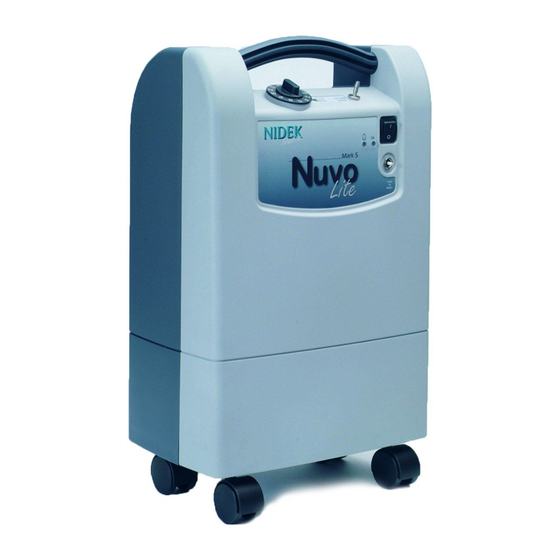
Mark 5 Nuvo® Lite Family
(Nuvo Lite and Nuvo Lite 3)
For models: 520, 525, 535, 920, 925, and 935
And serial numbers beginning 132-XXXXX
Nidek Medical Products, Inc.
3949 Valley East Industrial Drive Birmingham, Alabama 35217 USA
Telephone: (205) 856-7200 • 24-Hour Fax: (205) 856-0533
Nidek Medical is a trademark of Nidek Medical Products, Inc.
Mark 5 Nuvo® is a registered trademark of Nidek Medical Products, Inc
2010-8407 Rev E
April 30, 2018
Page 1 of 35
Advertisement
Table of Contents
Troubleshooting

Related Manuals for Nidek Medical Mark 5 Nuvo Lite Series


Summary of Contents for Nidek Medical Mark 5 Nuvo Lite Series
- Page 1 3949 Valley East Industrial Drive Birmingham, Alabama 35217 USA Telephone: (205) 856-7200 • 24-Hour Fax: (205) 856-0533 Nidek Medical is a trademark of Nidek Medical Products, Inc. Mark 5 Nuvo® is a registered trademark of Nidek Medical Products, Inc 2010-8407 Rev E April 30, 2018...
-
Page 2: Table Of Contents
Contents General Safety Warnings............................4 Glossary of Symbols ............................... 5 About the Mark 5 Nuvo Lite Family ........................6 Intended Use and Operation ..........................6 Installation and Storage ............................. 6 Alarms and Safety Features ..........................7 Device Performance and Specifications ......................8 Service Provider (Home / Clinic / Hospital) ...................... - Page 3 5.3.10 Replace Circuit Board (OCSI and Pressure) ..................... 19 5.3.11 Adjust Regulator ............................20 5.3.12 Clean / Rebuild Regulator ........................20 5.3.13 Replace Circuit Breaker ........................... 21 5.3.14 Replace Power Switch ..........................21 5.3.15 Replace Buzzer ............................21 5.3.16 Replace Hour Meter ..........................21 5.3.17 Replace Flow Valve ..........................
-
Page 4: General Safety Warnings
1.0 General Safety Warnings This unit is not a life-support device. Geriatric, pediatric, or any other patient unable to communicate discomfort while using this device should receive additional monitoring. This device supplies highly concentrated oxygen enriched product gas that promotes rapid burning. DO NOT allow smoking or open flames within the same room of this device or the administration accessory (cannula). -
Page 5: Glossary Of Symbols
2.0 Glossary of Symbols ON (Power switched on) OFF (Power switched off) Manufacturer Name and Address Type B Device Class II Protection IPX1 Protection from vertically falling water drops Do Not Expose to Open Flames Do Not Expose to Oil or Grease Tools Required / Technician Only Refer to Technical Information / Service Manual Refer to Instructions for Use / User’s Guide... -
Page 6: About The Mark 5 Nuvo Lite Family
3.0 About the Mark 5 Nuvo Lite Family 3.1 Intended Use and Operation The Mark 5 Nuvo Lite Family (Nuvo Lite and Nuvo Lite 3) Oxygen Concentrators are used as a means of providing continuous oxygen enriched product gas for patients, adolescent to geriatric, suffering from health conditions that cause low levels of oxygen in the blood (hypoxaemia). -
Page 7: Alarms And Safety Features
Consult your equipment provider for further information regarding altitudes of 2200 m to 4000m (7500 to 13000ft). The device should be stored in a dry area, with an ambient temperature between -20°C to 60°C (0°F to 140°F) at 15- 95% relative humidity. -
Page 8: Device Performance And Specifications
3.4 Device Performance and Specifications The performance of the device (especially the oxygen concentration) is quoted at 21°C (70°F) and one atmosphere. The specifications may change with temperature and altitude. Model 3 LPM 3 LPM Description 5 LPM 115V 5 LPM 230V 115V 230V Frequency... -
Page 9: Service Provider (Home / Clinic / Hospital)
Be available to service each patient at any time. • Keep service records of each device. A form approved by Nidek Medical has been provided in Appendix A. • Repair components and replace parts only as outlined in this manual. Use only Nidek Medical parts for replacement. - Page 10 2. Oxygen analyzers are available for purchase from Nidek Medical (see §5.4 for testing equipment part numbers).
-
Page 11: Patient / Caregiver Instruction
Refer to §5.2 for the Troubleshooting Chart for a list of problems, possible causes and solutions. • Keep service records of each device. A form approved by Nidek Medical has been provided in Appendix A. • Repair components and replace parts only as outlined in this manual. Use only Nidek Medical parts for replacement. - Page 12 c. Connect the pressure test gauge to the P1 test port. d. Observe the maximum and minimum readings on the pressure test gauge. i. Higher than normal operating pressure may indicate a restrictive exhaust muffler, which does not allow the waste (purge) gas to exit the system freely, or contaminated sieve beds. ii.
- Page 13 PRODUCT OUT TO FLOW CONTROL INLET FROM VALVE COMPRESSOR Figure 5.1.1 Normal Operating Configuration P2 TEST PORT P1 TEST PORT 5.1.2 Test Port Configuration 2010-8407 Rev E April 30, 2018 Page 13 of 35...
- Page 14 Low Oxygen Concentration Verify Oxygen Flow Rate Measure Air Pressure Low Pressure High Pressure Replace Air Inlet Filter Replace Muffler Check for Foams Leaks Check Check the Control Compressor Valve Normal Air Pressure Measure the Oxygen Pressure Low Pressure High Pressure Replace Check for Muffler...
-
Page 15: Troubleshooting Chart
5.2 Troubleshooting Chart PROBLEMS POSSIBLE CAUSES SOLUTIONS Defective sieve beds. Replace sieve beds. Compressor runs with intermittent high pressure alarm Restriction in exhaust muffler. Replace or clean muffler. and low oxygen concentration. Defective valve. Replace sieve module. Defective control valve. Replace sieve module. -
Page 16: Component Removal / Replacement Instruction
For your safety, be sure to set power switch to O (OFF) position and unplug the power cord before you service the device. Keep service records of each device. A form approved by Nidek Medical has been provided in Appendix A. 5.3.1 Remove Cabinet Back The cabinet back consists of a lower section and an upper section. -
Page 17: Replace Inlet / Silencer Filter
2. Pull the caster straight out away from the bottom. 5.3.3 Replace Inlet / Silencer Filter The inlet air filter requires inspection at each patient visit. The filter should be replaced every 2 years, or more often depending on environment. (The filter may require more frequent cleaning if the device operates in a harsh environment such as a house heated by wood, kerosene, or oil, or one with excessive cooking, cigarette smoke or atmospheric dust.) -
Page 18: Replace Capacitor
There are four bearings located within the compressor that allow the inner components of the compressor to rotate. If the bearings wear to the point that they become loose and noisy, the compressor becomes noticeably loud and needs servicing. The life of a compressor is determined primarily by its operating temperature. -
Page 19: Replace Cabinet Fan
It is recommended to replace the sieve beds and control valve as a complete assembly. To replace the sieve module, take the following steps: 1. Remove the upper cabinet back (§5.3.1). 2. Disconnect the compressor discharge 5/16” tube from the top of the solenoid valve and the product tube from the regulator. -
Page 20: Adjust Regulator
The OCSI board is different from the Pressure Monitoring board found in standard units (models 520 and 920). To replace the circuit board, take the following steps: 1. Remove the upper cabinet back (§5.3.1). 2. Remove the flow control valve (§5.3.17). 3. -
Page 21: Replace Circuit Breaker
5. Use a hex-head screwdriver to unscrew the diaphragm stem guide located in the center of the regulator body to gain access to the seat. 6. Remove the seat. Be careful not to lose the spring located behind the seat. 7. -
Page 22: Replace Flow Valve
Phillips head screwdriver, 8-inch adjustable wrench, 7/16-inch socket, 7/16-inch combination wrench, 5/8-inch combination wrench and 3/8-inch combination wrench. To check the oxygen concentration levels, Nidek Medical has an oxygen analyzer available for purchase: PN 6500-04225 – Maxtec UltraMax An accurate pressure test gauge to take both P-1 and P-2 pressure readings should be kept available at all times. -
Page 23: Schematics / Assembly Drawings / Part Callouts
6.0 Schematics / Assembly Drawings / Part Callouts 6.1 Flow Schematic (OCSI models) 6.2 Flow Schematic (Standard models) 2010-8407 Rev E April 30, 2018 Page 23 of 35... -
Page 24: Electrical Schematic (All Models)
6.3 Electrical Schematic (all models) Notes: Compressor Resistance 230V: ~290 Ohms 115V: ~ 10 Ohms Fan Resistance 230V: ~715 Ohms 115V: ~275 Ohms Wire Colors R = Red BL = Blue BR = Brown GR = Green YL = Yellow 230 V shown with jumper from terminal 2 to 3 on J2. -
Page 25: Compressor Assembly / Parts Callout
6.4 Compressor Assembly / Parts Callout 2010-8407 Rev E April 30, 2018 Page 25 of 35... - Page 26 Reference I.D. Description Unit Req’d 8400-1513 SHUNT, VOLTAGE SELECTION 8400-0110 BRACKET,COMPRESSOR 8400-0154 FITTING COMPR to Blue Tube 8400-0116 SPRING, COMPRESSION 8400-2162 TUBING, 3/8OD One Formed 90EL 9250-1330 CORD, POWER, EUROPLUG 230 V 9250-1311 CORD,POWER, TYPE "K" PLUG, 115 V US 8400-1332 CORD, POWER, CHINA 230 V 8400-1340...
-
Page 27: Front Cabinet Assembly / Parts Callout
6.5 Front Cabinet Assembly / Parts Callout 2010-8407 Rev E April 30, 2018 Page 27 of 35... - Page 28 Reference I.D. Description Unit Req’d 8400-0102 CABINET, FRONT 8400-0104 COVER, RESONATOR 8400-0107 O-RING, RESONATOR COVER 8400-1700 VALVE, FCV 1/8-5.0 LPM 8400-1331 KNOB,FLOW 0.125 TO 5.0 FLOW 9251-1332 RING,LOCK-OUT 9251-1335 CLIP,D STYLE 8400-1020 FITTING, OXYGEN OUTLET 8400-0128 HOSE, COMPRESSOR SUCTION 8400-1029 NUT 3/8-24 O2 OUTLET LITE FILTER, FINAL PRODUCT 7631-1053...
-
Page 29: Back Cabinet Assembly / Parts Callout
6.6 Back Cabinet Assembly / Parts Callout 2010-8407 Rev E April 30, 2018 Page 29 of 35... - Page 30 Reference I.D. Description Unit Req’d 8400-0101 CABINET, BACK LOWER 8400-0103 CABINET, BACK UPPER 8400-1025 FILTER,CABINET INLET 8400-0108 FILTER FRAME 8400-0022 RETAINER, CORD HOOK&LOOP 8400-0029 RETAINER,CORD BUCKLE 8400-0023 RETAINER,CORD RIVET 8400-1180 FILTER AIR COMPRESSOR 8400-0113 MODULE BUMPER 8400-0114 CLAMP, POWER CORD 8400-0115 SCREW, #14x 1"LG PLASTITE 2010-8407 Rev E...
-
Page 31: Module Assembly / Parts Callout
6.7 Module Assembly / Parts Callout 2010-8407 Rev E April 30, 2018 Page 31 of 35... - Page 32 Reference I.D. Description Unit Req’d REGULATOR, 2-PORT (No Longer Used 8400-2060 Replaced by 8400-1060) REGULATOR, 2-PORT (No Longer Used 8400-1060 Replaced by 8400-1060) FITTING VALVE 5/16"X3/8 (No Longer Used Replaced by Blue Tube with Formed 90EL 8400-1165 8400-1162, which has been replaced by 8400-2162)) 8400-1200 VALVE ASSY...
-
Page 33: Appendix A Service And Maintenance Log
Appendix A Service and Maintenance Log Nidek Medical Oxygen Concentrator Service and Maintenance Log Model Number ________________ Serial Number ___________________ Initial Inspection Routine Service Check 1. Upon receipt, check the unit for shipping Perform routine servicing as shown in the chart below. - Page 34 Nidek Medical Oxygen Concentrator Service and Maintenance Log Please maintain a log of all maintenance activities Model _____________ performed on this unit. Serial Number___________________ Date Hours % O2 Alarms Additional Information Check (Work Done, Filter Changes, Comments, etc) Inspection Prior to Putting Into Service...
-
Page 35: Conformity With En 60601-1
60601-1-2 standard. EU Representative mdi Europa GmbH Langenhagener Str. 71 30855 Hannover-Langenhagen Germany Tel: +49-511-39-08 95 30 Nidek Medical Products, Inc. Fax: +49-511-39-08 95 39 3949 Valley East Industrial Drive info@mdi-europa.com Birmingham, Alabama 35217 U.S.A. www.mdi-europa.com Tel: 205-856-7200 Fax: 205-856-0533...
Need help?
Do you have a question about the Mark 5 Nuvo Lite Series and is the answer not in the manual?
Questions and answers