Table of Contents
Advertisement
Quick Links
Advertisement
Table of Contents

Related Manuals for Ametek 4207D


Summary of Contents for Ametek 4207D
- Page 1 OPERATING MANUAL MODEL 4207D DIGITAL COMPRESSIVE STRENGTH TESTER Revision N – February 2023 P/N: 89-0164 S/N: ____________ 2001 N. Indianwood Ave. Broken Arrow, Oklahoma 74012 U.S.A. Telephone: 918-250-7200 Fax: 918-459-0165 E-mail: chandler.sales@ametek.com Website: http://www.chandlereng.com...
- Page 2 This publication contains the following trademarks and/or registered trademarks: AMETEK, CHANDLER ENGINEERING. These trademarks or registered trademarks and stylized logos are all owned by AMETEK, Inc. All other company, product and service names and logos are trademarks or service marks of their respective owners.
-
Page 3: Table Of Contents
TABLE OF CONTENTS Table of Contents General Information ............... P-1 Introduction ........................... P-1 Purpose and Use ....................P-1 Description ......................P-1 Features and Benefits ......................P-1 Specifications ........................P-1 Safety Requirements ......................P-2 Safety Features ........................P-3 Where to Find Help ....................... P-3 Section 1 –... -
Page 5: General Information
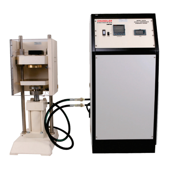
General Information Introduction The Model 4207D Digital Compressive Strength Tester is a hydraulic press system that may be used to apply known compressive loads to a sample at known rates. The maximum load is 50,000 Lbf. The Model 4207D Tester meets all the requirements for cement compressive testing as specified in API Specification 10. -
Page 6: Safety Requirements
Note: Before attempting to operate the instrument, the operator should read and understand this manual. The Chandler Engineering Model 4207D Digital Compressive Strength Tester is designed for operator safety. Any instrument that is capable of high pressures should always be operated... -
Page 7: Safety Features
Where to Find Help In the event of problems, your local sales representative will be able to help or you can contact the personnel at Chandler Engineering using the following: • Telephone: 918-250-7200 • FAX: 918-459-0165 • E-mail: chandler.sales@ametek.com • Website: www.chandlereng.com... - Page 8 PREFACE This page is intentionally left blank...
-
Page 9: Section 1 - Installation
Electrical: 200-240 VAC, 50 Hz or 60 Hz, depending on model. Tools/Equipment Required No special tools are required for the installation of the Model 4207D. Standard hand tools are sufficient. Connecting Power Connect the power cord to an approved grounded receptacle in accordance with local wiring codes. -
Page 10: Connecting The Press To The Power Unit
SECTION 1 – INSTALLATION The system power switch on the front panel also serves as a circuit breaker. If the breaker trips, correct the electrical problem then reset the breaker by cycling the switch. Connecting the Press to the Power Unit There are three connections between the load frame and the control cabinet, 2 hydraulic lines and a 25-pin cable connection. -
Page 11: Section 2 - Operating Instructions
SECTION 2 – OPERATING INSTRUCTIONS Section 2 - Operating Instructions Before operating the 4207D it is necessary to be familiar with the pressure controller. Programming the Controller The Model 9050 controller used with the 4207D system features user defined segment programming (8 segments maximum). - Page 12 SECTION 2 – OPERATING INSTRUCTIONS Program Status: Indicates the current Program Step: Indicates Ramp / Step Up Indicates Dwell (Flashing indicates Dwell End) Indicates Ramp / Step Down. Manual Mode: Indicates Manual Mode has been selected. In Manual Mode, the Raise and Lower buttons operate on the Output Power.
- Page 13 SECTION 2 – OPERATING INSTRUCTIONS Press the “Page” button until P.SET is displayed Press “Scroll”; Observe P.NUM (Program Number) 1 is indicated Press “Scroll”; Verify that HB.STY (Holdback Style) is set to PROG. Press “Scroll”; Verify that HB.TYP (Holdback Type) is set to OFF. Press “Scroll”;...
-
Page 14: Operating Procedure
SECTION 2 – OPERATING INSTRUCTIONS 26. Press “Scroll”; Set S.TYPE (Segment Type) to “dwEL” (Dwell). 27. Press “Scroll”; Set DUR (Duration) to 2:00 (2 minutes) 28. Press “Scroll”; Observe that S.NUM is now 5. 29. Press “Scroll”; Observe that S.NAME is now S5. 30. - Page 15 SECTION 2 – OPERATING INSTRUCTIONS Note: For low compressive strength samples 8.0-12.0 min is the recommended duration. For high compressive strength samples 2.0-3.0 min is the recommended duration. 9. Place the press direction control switch in the UP position. 10. Increase the controller output to 1.0% by pressing the UP arrow button. The press will rise, contact the upper platen and stop.
-
Page 16: Interpreting The Results
SECTION 2 – OPERATING INSTRUCTIONS 18. Place the press direction control switch in the DOWN position to lower the platen for cleaning. 19. Place the press direction control switch in the OFF position. 20. Open the safety door, dispose of the sample. 21. - Page 17 SECTION 2 – OPERATING INSTRUCTIONS This page is intentionally left blank...
-
Page 18: Section 3 - Maintenance
SECTION 3 – MAINTENANCE Section 3 – Maintenance Maintenance Schedule MAINTENANCE SCHEDULE Model 4207D Digital Compressive Strength Tester COMPONENT EACH TEST MONTHLY 3 MONTHS 6 MONTHS ANNUAL Check Level Every two years, change the oil System Pressure Check the system... -
Page 19: Resetting The Maximum Temperature Limit
SECTION 3 – MAINTENANCE Note: The system pressure will decrease as the oil temperature increases. For this reason, adjust the system pressure when the oil temperature is at or near room temperature. 1. Verify that the system temperature is below 80F (27C). Gauge 2. -
Page 20: Maintaining The Press Assembly
SECTION 3 – MAINTENANCE Maintaining the Press Assembly Use the following procedure to inspect the condition and safety of the press assembly: 1. Verify that the door limit switch is operational. 2. Inspect the cylinder and repair any leaks. 3. Inspect the hydraulic hoses and replace if signs of deterioration exist. 4. -
Page 21: Calibration
4. Replace the cover plate. Calibration The 4207D uses a Linearization Table to calibrate the load cell. This table can be edited from the Chandler 5270 software or at the Controller. Refer to procedure 89-0200 (PROC,4207D LINEARIZATION) for detailed instructions. - Page 22 SECTION 3 – MAINTENANCE This page is intentionally left blank...
-
Page 23: Section 4 - Troubleshooting Guide
SECTION 4 - TROUBLESHOOTING GUIDE Section 4 - Troubleshooting Guide Symptom Reason Action Press does not operate. Load frame door is open. Close the load frame door. Over-temperature circuit has Reset the over-temperature disabled the system. circuit by pressing the red button on the side panel. - Page 24 SECTION 4 – TROUBLESHOOTING GUIDE Symptom Reason Action Sample fails prematurely. Initial sample load is excessive. Check the adjustment of the top platen limit switch. Adjust the top platen control switch to close before the platen touches the top of the press. Verify the time delay relay is set to approx.
-
Page 25: Section 5 - Replacement Parts
SECTION 5 - REPLACEMENT PARTS Section 5 - Replacement Parts Part Number Description 07-0176 Thermocouple Assembly C11149 Filter Element P-1130 Fuse, 1A P-1662 Fuse, 2A P-3431 Relay, Solid-State, DC Control... - Page 26 SECTION 5 – REPLACEMENT PARTS This page is intentionally left blank...
-
Page 27: Section 6 - Drawings And Schematics
CONTROLLER CONFIGURATION Section 6 – Drawings and Schematics Document Number Description 89-0151 Wiring Diagram 89-0170 4207D Pump Connections 89-0175 Procedure, 5270 Configuration... - Page 30 Using Tools > Configure > I/O Connections, configure an I/O connection using the Modbus protocol. Select the COM port that is connected to the 4207D instrument. COM4 is illustrated; however, the actual port assignment may vary as required by the hardware configuration.
- Page 31 TITLE: Procedure, 5270 Configuration for 4207D Instrument Model: Model 4207D Compressive Strength Tester Using Tools > Configure > Instruments, select the Model 4207D Compressive Strength Tester from the list of available instruments. Assign a name and file prefix. These choices may vary as desired.
- Page 32 cut out postcards on dotted lines Please Send Us Your Comments on This Manual Model Number ____________________________ Serial Number __________________________ Printing Date of this manual (from the Title Page) ______________ Please circle a response for each of the following statements. Use: (1)= Strongly agree (2) =Agree (3) =Neutral, no opinion (4) =Disagree (5) =Strongly disagree a) The manual is well organized.
- Page 33 cut out postcards on dotted lines...
- Page 34 4903 W. Sam Houston Parkway, N., Suite A-400, Houston, TX 77041 2001 North Indianwood Avenue, Broken Arrow, OK 74012 Tel: +1 713-466-4900 Fax: +1 713-849-1924 Tel: +1 918-250-7200 Fax: +1 918-459-0165 e-mail: chandler.sales@ametek.com www.chandlereng.com Printed in the U.S.A. © 2008, by AMETEK, Inc. All rights reserved. XM808PDF (360000)
Need help?
Do you have a question about the 4207D and is the answer not in the manual?
Questions and answers