Table of Contents

Related Manuals for Ametek NSG 4070C1


Summary of Contents for Ametek NSG 4070C1
- Page 1 NSG 4070C1 QUICK-START GUIDE AND SAFETY INSTRUCTIONS NSG 4070C1-35 NSG 4070C1-45 NSG 4070C1-60 NSG 4070C1-80 NSG 4070C1-110 NSG 4070C1-0 Version: Replaces: Filename: NSG_4070C1_quick_start_manual en Print date: 03 May 20223 May 2022...
- Page 2 12623 Berlin, Germany Landsberger Str. 255 Phone: + 49 30 5659 8835 Fax: + 49 30 5659 8834 URL : www.ametek-cts.com Copyright © 2022 AMETEK CTS GmbH All right reserved. Specifications subject to change. Quick Start and Safety Guide 2 / 20...
-
Page 3: Table Of Contents
AMETEK CTS NSG 4070 Table of Contents Safety ............................4 Safety and warning symbols ........................4 Safety Aspects ............................4 Connection to the mains and PE ........................ 5 Connections to other ports with dangerous voltages (AE, EUT, RF port ...) ..........5 Connection to the ground plane or Faraday cage .................. -
Page 4: Safety
The user must obey all safety instructions and warnings. Neither AMETEK CTS Europe GmbH nor any of its subsidiary sales organizations can accept any responsibility for personal, material or consequential injury, loss or damage that results from improper use of the equipment and accessories. -
Page 5: Connection To The Mains And Pe
AMETEK CTS NSG 4070 Connection to the mains and PE The instrument conforms to protection class 1. Operation without a protective earth connection is forbidden! Before switching on the device, check whether the selected voltage matches the supply voltage. The posi- tion of the voltage selector must correspond with the mains. -
Page 6: Operating Environment
AMETEK CTS NSG 4070 To reduce the risk of electric shock, do not remove parts from the housing. There are no user serviceable parts inside the unit. Certain parts inside the instrument work at mains voltage or at high frequency and are not provided with any protection against being touched. -
Page 7: Dangers Concerning The Generator
AMETEK CTS NSG 4070 1.11 Dangers concerning the generator Local regulations for the protection of radio services must be observed. The interference generated by the generator can cause both conducted and radiated interference. If the radiated energy exceeds the permissible level, a shielded chamber with filtering of the supply lines or similar must be used. -
Page 8: Warranty Terms
AMETEK CTS will, at its expense, deliver the repaired or replaced product or parts to the buyer. Any warranty of AMETEK CTS will not apply if the buyer is in default under the purchase order agreement or where the product or any part thereof: •... -
Page 9: Unpacking, Storage And Transport
AMETEK CTS NSG 4070 Unpacking, storage and transport General Save all packing materials! They will be needed in order to safely package the equipment for calibration service or repair. Packaging materials • Carton: Cardboard • Padding: CFC-free polystyrene foam •... -
Page 10: Description Of The Instrument
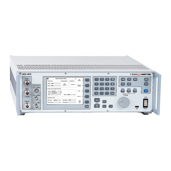
The NSG 4070C1 includes extended parameters for the pulse modulation. Up to three pulse modulation settings can be defined in order to create an envelope. NSG 4070C1 meets the requirements of ISO / DTS 7637-4 Annex C: Test generator for pulsed sinusoidal disturbances, pulse A. - Page 11 AMETEK CTS NSG 4070 Figure 2. - Front panel and operating elements Power on key, hard key, switching takes effect with a short delay The LED next to the switch will turn from yellow to green when the unit is switched on.
- Page 12 AMETEK CTS NSG 4070 Figure 3. - Back panel Power supply connector for wide range supply: 110 / 230 Volts, 50 / 60 Hz autoranging. Fuse F1, see technical specifications for selection guide of fuse F1 User port D-Sub 15 pole RS232 - interface for remote control of the NSG 4070 using a null modem connection...
-
Page 13: Quick Start
AMETEK CTS NSG 4070 Quick Start Quick Start and Safety Guide 13 / 20... - Page 14 AMETEK CTS NSG 4070 Quick Start and Safety Guide 14 / 20...
- Page 15 AMETEK CTS NSG 4070 Quick Start and Safety Guide 15 / 20...
-
Page 16: Remote
AMETEK CTS NSG 4070 Remote Connect the NSG 4070 with a suitable mains socket. Switch the unit on. Connect the NSG 4070 and USO 4013 to the PC. Press “Setup“. Press “Remote“. Press “RS232 optical“. Press “Back“ Press “Baudrate setup“... -
Page 17: Applications
AMETEK CTS NSG 4070 Applications IEC 61000-4-6 System calibration with CDN Testing with CDN System calibration with EM clamp or CIP Testing with EM clamp or CIP Saturation check Quick Start and Safety Guide 17 / 20... -
Page 18: Bci According Iso 11452-4
AMETEK CTS NSG 4070 BCI according ISO 11452-4 System calibration Substitution testing Closed-Loop testing BCI according MIL-STD-461G CS114, example Level 2, 5, 5 System calibration Verification Quick Start and Safety Guide 18 / 20... -
Page 19: Iso/Dts 7637-4 Pulse A
AMETEK CTS NSG 4070 Testing ISO/DTS 7637-4 Pulse A System calibration Testing ISO 11452-5 System calibration Closed-Loop testing Quick Start and Safety Guide 19 / 20... -
Page 20: Maintenance
The NSG 4070 including accessories does not require any special maintenance. Maintenance is limited to cleaning the con- tacts and air inlets and outlets. The service life of the connectors is limited due to the durability of the contacts. AMETEK CTS can replace the worn connectors.
Need help?
Do you have a question about the NSG 4070C1 and is the answer not in the manual?
Questions and answers