Table of Contents
Advertisement
Quick Links
Introduction
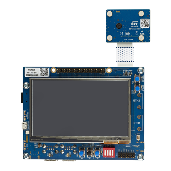
The STM32MP135 Discovery kit (STM32MP135F-DK) is designed as a complete demonstration and development platform for
®
the STMicroelectronics Arm
chip. It leverages the capabilities of the 1 GHz STM32MP135 microprocessors to allow users to develop easily applications
using STM32 MPU OpenSTLinux Distribution software (such as STM32MP1Starter).
It features 16-bit DDR3L 4 Gbits at 533 MHz, MIPI CSI-2
Type-A Host HS ports, microSD
®
Wi‑Fi
802.11b/g/n, Bluetooth
The STM32MP135F-DK, shown in
cannot be considered as the hardware design of a final application.
The hardware features of the Discovery kit are available for users to develop their applications: USB, dual Ethernet, LCD,
™
microSD
card, user buttons, Wi‑Fi
allow the easy connection of a third-party board for a specific application.
An STLINK-V3E is integrated on the board, as an embedded in-circuit debugger and programmer for the STM32 MPU and the
USB Virtual COM port bridge.
Figure 1.
STM32MP135F-DK top view
Pictures are not contractual.
UM2993 - Rev 2 - March 2023
For further information contact your local STMicroelectronics sales office.
Discovery kit with 1 GHz STM32MP135FA MPU
®
‑A7 32-bit
-based single Cortex
®
™
card high-speed mode up to 50 MHz, dual 10/100 Mbit/s Ethernet, 40-pin extended GPIOs,
®
Low Energy 4.1, and STLINK-V3E (UART console).
Figure 1
and
Figure
2, is used as a reference design for the user application development. It
®
®
, Bluetooth
Low Energy, and a 2-megapixel CMOS camera module. Extension headers
STM32MP135
microcontrollers and their
bridge with dual lanes up to 1.6 Gbit/s, USB Type-C
Figure 2.
STM32MP135F-DK bottom view
UM2993
User manual
STPMIC1
companion
®
DRP port, USB
www.st.com
Advertisement
Table of Contents

Related Manuals for ST STM32MP135F-DK


Summary of Contents for ST STM32MP135F-DK
-
Page 1: Figure 1. Stm32Mp135F-Dk Top View
UM2993 User manual Discovery kit with 1 GHz STM32MP135FA MPU Introduction The STM32MP135 Discovery kit (STM32MP135F-DK) is designed as a complete demonstration and development platform for ® ® ‑A7 32-bit the STMicroelectronics Arm -based single Cortex STM32MP135 microcontrollers and their... -
Page 2: Features
‑A7 32-bit processor at 1 GHz, in a TFBGA320 package ® ® • STM32MP135FAF7 MPU with an Arm Cortex • ST PMIC STPMIC1 • 4-Gbit DDR3L, 16 bits, 533 MHz • 4.3" 480×272 pixels LCD display module with capacitive touch panel and RGB interface ®... -
Page 3: Ordering Information
Codification The meaning of the codification is explained in Table Table 2. Codification explanation STM32TTTXXY-ZZ Description Example: STM32MP135F-DK STM32TTT MPU series in STM32 Arm Cortex MPUs STM32MP1 series MPU product line in the series STM32MP135 Options: Secure boot, cryptography hardware, •... -
Page 4: Development Environment
The STM32 MPU OpenSTLinux Distribution base demonstration software is preloaded in the microSD for easy demonstration of the device peripherals in standalone mode. The latest versions of the demonstration source code and associated documentation can be downloaded from www.st.com. UM2993 - Rev 2 page 4/42... -
Page 5: Conventions
UM2993 Conventions Conventions Table 3 provides the conventions used for the ON and OFF settings in the present document. Table 3. ON/OFF convention Convention Definition Resistor Rx ON Resistor soldered Resistor Rx OFF Resistor not soldered UM2993 - Rev 2 page 5/42... -
Page 6: Safety Recommendations
UM2993 Safety recommendations Safety recommendations Targeted audience This product targets users with at least basic electronics or embedded software development knowledge like engineers, technicians, or students. This board is not a toy and is not suited for use by children. Handling the board This product contains a bare printed circuit board. -
Page 7: Quick Start
UM2993 Quick start Quick start This chapter describes how to start a development quickly using the STM32MP135F-DK. Before installing and using the product, accept the evaluation product license agreement from the www.st.com/ epla webpage. Before the first use, make sure that no damage occurred to the product during shipment and check that: •... -
Page 8: Hardware Layout And Configuration
3) illustrates the connection between the STM32MP135FAF7 ® microprocessor and the peripherals (such as dual Ethernet, MIPI CSI-2 camera module connector, USB Type- ® DRP and USB Type-A connectors, GPIO expansion, and embedded ST-LINK). Figure 3. STM32MP135F-DK hardware block diagram STM32MP135F 5V_VIN USB Type-C ®... -
Page 9: Figure 4. Stm32Mp135F-Dk Pcb Layout: Top Side
UM2993 Hardware layout Figure 4 Figure 5 show the locations of these features on the STM32MP135F-DK. Figure 4. STM32MP135F-DK PCB layout: top side 40-pin connector User button 1 (CN8) (B1) User LED (LD3) User LED (LD4) User button 2 (B2) 4.3"... -
Page 10: Figure 5. Stm32Mp135F-Dk Pcb Layout: Bottom Side
UM2993 Hardware layout Figure 5. STM32MP135F-DK PCB layout: bottom side STMIPID02 CSI connector de-serializer LCD backlight power supply (CN1) (U2) (U9) Wi-Fi ® / BLE (U1) microSD™ Ethernet 2 card (CN15) (CN3) Ethernet 2 PHY (U7) STM32 ST-LINK (U12) Ethernet 1 PHY... -
Page 11: Hardware Configuration
In cases where the STM32MP135F-DK Discovery kit is connected to the PC before the driver is installed, some STM32MP135F-DK interfaces may be declared as “Unknown” in the PC device manager. In this case, the user must install the dedicated driver files, and update the driver of the connected device from the device manager. -
Page 12: Power Supply
UM2993 Power supply Power supply 7.4.1 5 V power supply The STM32MP135F-DK Discovery kit is designed to be powered by a 5 V DC power source at 3 A maximum such as: ® ® • 5V_VBUS connected to the CN12 connector through a USB Type-C... -
Page 13: Reset Sources
UM2993 Reset sources Reset sources The reset signal of STM32MP135F-DK is active low. The internal PU forces the RST signal to a high level. The sources of reset are: • Reset button B5 (black button) • STPMIC1 • Embedded STLINK-V3 •... -
Page 14: Usb Host
USB Host 7.8.1 Description STM32MP135F-DK provides four USB Host ports (dual-USB Type-A sockets CN5 and CN6) through the use of the USB hub. The USB hub has a full power management for each USB port: no I/O is needed from the STM32MP135FAF7. -
Page 15: Usb Type-C ® Hs
VBUS VBUS USB1CN25_N USB1CN25_P ® USB Type-C 7.9.1 Description The STM32MP135F-DK Discovery kit supports USB high speed (HS) communication. USB connector CN7 is a ® USB Type-C connector. ® The STM32MP135F-DK Discovery kit supports the USB Type-C Source mode. 7.9.2 Operating voltage The STM32MP135F-DK Discovery kit supports 5 V USB voltage from 4.75 V to 5.25 V. -
Page 16: Microsd ™ Card
3.3 V voltage range: from 2.7 V to 3.6 V. All microSD card types are supported (including SDHC and SDXC), but only Default and High-Speed modes (3V3) are supported on STM32MP135F-DK. UHS-I modes (1.8 V) are not supported on this Discovery kit. 7.10.3 ™... -
Page 17: Leds
UM2993 LEDs ™ Figure 8 shows the pinout of the microSD card connector CN3. ™ Figure 8. microSD card connector CN3 ™ Table 10 describes the pinout of the microSD card connector CN3. ™ Table 10. CN3 microSD card connector pinout Pin name Signal name STM32 pin... -
Page 18: Operating Voltage
MCP IO15 is connected to the orange LED LD6. Active High. 7.12 Buttons 7.12.1 Description The STM32MP135F-DK Discovery kit provides five buttons: • USER1 button (B1) – Used at boot time by U-Boot to enter the USB programming mode •... -
Page 19: Csi-Dcmi
CSI-DCMI 7.13.1 Description The STM32MP135F-DK Discovery kit provides an external camera module with a 1/4" color CMOS UXGA 2-megapixel image sensor. A CSI-DCMI bridge deserializes data from the camera module, which are then transmitted to the MPU. The resolution is up to 1600 x 1200 with 20 frames per second. -
Page 20: Table 14. Csi Interface And Cn1 Connector Pinout
UM2993 CSI-DCMI Figure 9 shows the pinout of CSI connector CN1. Figure 9. CN1 CSI connector pinout Table 14 describes the CSI interface and pinout of CSI connector CN1. Table 14. CSI interface and CN1 connector pinout STM32 pin Signal name Function Negative data lane 1 from MIPI-CSI DATA1_N... -
Page 21: Wi-Fi ® And Bluetooth ® Low Energy
Bluetooth Low Energy 7.14.1 Description ® ® The STM32MP135F-DK Discovery kit supports Wi‑Fi 802.11b/g/n and Bluetooth Low Energy (BLE) V4.1. This ® ® module is driven by an SDIO for the Wi‑Fi interface, and a USART for the Bluetooth . -
Page 22: Lcd
UM2993 7.15 The LCD is provided and mounted with the STM32MP135F-DK Discovery kit. 7.15.1 Description The TFT LCD module is connected to the board through the 40-pin connector CN16. The touch panel is embedded in the LCD module. The LCD module is composed of a TFT LCD module with an LCD driver. The 4.3" LCD supports a resolution of 480 ×... -
Page 23: Dual 10/100Mbit/S Ethernet
Dual 10/100Mbit/s Ethernet 7.16.1 Description The STM32MP135F-DK Discovery kit provides a reduced media-independent interface (RMII). STM32MP135FAF7 requires an external physical interface device (PHY) for each RMII. The Ethernet PHY on the Discovery kit is connected to the physical LAN bus using 10 or 11 signals for RMII on Wake on LAN (WoL) support. -
Page 24: Gpio Expansion Connector Interface
UM2993 GPIO expansion connector 7.17.2 GPIO expansion connector interface Figure 10 shows the pinout of the CN8 GPIO connector. Figure 10. CN8 GPIO connector CN8 pin 1 CN8 pin 2 UM2993 - Rev 2 page 24/42... -
Page 25: Vbat Connector
UM2993 VBAT connector Table 18 describes the pinout of the CN8 GPIO connector. Table 18. CN8 GPIO connector pinout Function STM32 pin STM32 pin Function GPIO2 / I2C5_SDA GPIO3 / I2C5_SCL GPIO4 / TIM3_CH4 GPIO14 / USART1_TX GPIO15 / USART1_RX GPIO17 / USART1_RTS GPIO18 / SAI1_SCKA GPIO27 / DFSDM1_CKOUT... -
Page 26: Table 20. Cn11 Vbat Connector Pinout
UM2993 VBAT connector Figure 11 shows the pinout of the CN11 VBAT connector. Figure 11. CN11 VBAT connector pinout Table 20 describes the VBAT interface and pinout of connector CN11. Table 20. CN11 VBAT connector pinout Pin name Function VBAT VBAT supply. -
Page 27: Stm32Mp135F-Dk Product Information
B01. The second line shows the board serial number used for traceability. Parts marked as “ES” or “E” are not yet qualified and therefore not approved for use in production. ST is not responsible for any consequences resulting from such use. In no event will ST be liable for the customer using any of these engineering samples in production. -
Page 28: Board Revision History
UM2993 Board revision history Board revision history Table 22. Board revision history Board reference Board variant and revision Board change description Board limitations MB1635 (main board) MP135F-E02 Initial revision No limitation MB1897 (camera module board) CSI-B01 Initial revision No limitation UM2993 - Rev 2 page 28/42... -
Page 29: Stm32Mp135F-Dk I/O Assignment
UM2993 STM32MP135F-DK I/O assignment STM32MP135F-DK I/O assignment Table 23. STM32MP135 Discovery kit I/O assignment Ball Assignment DCMI_D0 PE11 USART2_CTS LCD_INT DCMI_D5 PE14 DCMI_D7 DCMI_D1 PH12 USART2_TX LCD_B6 UART4_TX DCMI_HSYNC DCMI_D6 PA12 ETH2_CRS_DV LCD_RST PD11 DCMI_D4 DCMI_VSYNC PF8_WKUP ETH2_CLK ETH2_MDC PG15... - Page 30 UM2993 STM32MP135F-DK I/O assignment Ball Assignment ETH2_TXD0 PG11 ETH2_TXD1 I2C5_SDA FDCAN2_TX MCO2 PH0-OSC_IN HSE_IN PH1-OSC_OUT HSE_OUT SPI5_MOSI FDCAN2_RX ETH1_MDC PG12 MCP_INT MCO1 PA13 PA13 (user button 2) PA11 ETH1_CLK PB11 ETH1_TX_EN PF14 STLINK_SWCLK SAI1_SDB PF13 DFSDM1_DATIN3 ETH1_RX_CLK ETH1_MDIO SAI1_SDA USART1_TX...
- Page 31 UM2993 STM32MP135F-DK I/O assignment Ball Assignment PA14 PA14 (user button 1) AA15 PI5-BOOT1 BOOT1 PI6-BOOT2 BOOT2 PI4-BOOT0 BOOT0 AA16 USB_DM1 USB_DM1 USB_DP1 USB_DP1 AA19 PA10 STM32G0_WAKE AA20 LCD_DISP uSD_DETECT STLINK_SWO SDMMC1_D1 SDMMC1_D0 SDMMC1_CMD PC12 SDMMC1_CK PC10 SDMMC1_D2 PC11 SDMMC1_D3 SDMMC2_CMD...
- Page 32 UM2993 STM32MP135F-DK I/O assignment Ball Assignment I2C1_SDA PD15 USART2_RX LCD_CLK LCD_G5 LCD_G4 UM2993 - Rev 2 page 32/42...
-
Page 33: Federal Communications Commission (Fcc) And Ised Canada Compliance
UM2993 Federal Communications Commission (FCC) and ISED Canada Compliance Statements Federal Communications Commission (FCC) and ISED Canada Compliance Statements 10.1 FCC Compliance Statement Part 15.19 This device complies with Part 15 of the FCC Rules. Operation is subject to the following two conditions: (1) this device may not cause harmful interference, and (2) this device must accept any interference received, including interference that may cause undesired operation. -
Page 34: Additional Fcc And Ised Canada Compliance Statements
UM2993 Additional FCC and ISED Canada Compliance Statements 10.3 Additional FCC and ISED Canada Compliance Statements Contains module from Murata model: LBEE5KL1DX-977 FCC ID: VPYLB1DX IC: 772C-LB1DX ISED Licence-Exempt Radio Apparatus This device contains license-exempt transmitter(s)/receiver(s) that comply with Innovation, Science and Economic Development Canada’s license-exempt RSS(s). -
Page 35: Ce Conformity
11.2 Simplified declaration of conformity Hereby, STMicroelectronics declares that the radio equipment types and STM32MP135F-DK are in compliance with Directive 2014/53/EU. The full text of the EU declaration of conformity is available from their product web page. -
Page 36: Revision History
UM2993 Revision history Table 24. Document revision history Date Revision Changes 01-Mar-2023 Initial release. Updated cover pictures. Updated board variant references in Table 21. Product history 06-Mar-2023 Table 22. Board revision history. Updated Section 10 Federal Communications Commission (FCC) and ISED Canada Compliance Statements. -
Page 37: Table Of Contents
UM2993 Contents Contents Features................2 Ordering information . - Page 38 UM2993 Contents USB Host ..............14 7.8.1 Description .
- Page 39 STM32MP135F-DK product information ........
-
Page 40: List Of Tables
UM2993 List of tables List of tables Table 1. List of available products............. . . 3 Table 2. -
Page 41: List Of Figures
STM32MP135F-DK hardware block diagram ........ - Page 42 ST’s terms and conditions of sale in place at the time of order acknowledgment. Purchasers are solely responsible for the choice, selection, and use of ST products and ST assumes no liability for application assistance or the design of purchasers’...
Need help?
Do you have a question about the STM32MP135F-DK and is the answer not in the manual?
Questions and answers