Table of Contents
Advertisement
All manuals and user guides at all-guides.com
UM1724
User manual
STM32 Nucleo boards
Introduction
The STM32 Nucleo board (NUCLEO-F030R8, NUCLEO-F072RB, NUCLEO-F103RB,
NUCLEO-F302R8, NUCLEO-F334R8, NUCLEO-F401RE, NUCLEO-F411RE, NUCLEO-
L053R8, NUCLEO-L152RE
provides an affordable and flexible way for users to try out new
)
ideas and build prototypes with any STM32 microcontroller lines, choosing from the various
™
combinations of performance, power consumption and features. The Arduino
connectivity support and ST Morpho headers make it easy to expand the functionality of the
Nucleo open development platform with a wide choice of specialized shields. The STM32
Nucleo board does not require any separate probe as it integrates the ST-LINK/V2-1
debugger/programmer. The STM32 Nucleo board comes with the STM32 comprehensive
software HAL library together with various packaged software examples, as well as direct
access to mbed online resources at mbed.org.
(1)
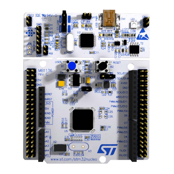
Figure 1. STM32 Nucleo board
1. Picture not contractual.
June 2014
DocID025833 Rev 4
1/55
www.st.com
Advertisement
Table of Contents

Related Manuals for ST STM32 NUCLEO-F030R8


Summary of Contents for ST STM32 NUCLEO-F030R8
-
Page 1: Figure 1. Stm32 Nucleo Board (1)
™ combinations of performance, power consumption and features. The Arduino connectivity support and ST Morpho headers make it easy to expand the functionality of the Nucleo open development platform with a wide choice of specialized shields. The STM32 Nucleo board does not require any separate probe as it integrates the ST-LINK/V2-1 debugger/programmer. -
Page 2: Table Of Contents
Embedded ST-LINK/V2-1 ........13... - Page 3 All manuals and user guides at all-guides.com UM1724 Contents 5.12 STMicroelectronics Morpho connector ......43 Mechanical drawing .
- Page 4 All manuals and user guides at all-guides.com List of tables UM1724 List of tables Table 1. Ordering information ............6 Table 2.
- Page 5 Connecting the STM32 Nucleo board to program the on-board STM32 ....15 Figure 8. Using ST-LINK/V2-1 to program the STM32 on an external application ....16 Figure 9.
-
Page 6: Ordering Information
All manuals and user guides at all-guides.com Ordering information UM1724 Ordering information Table 1 lists the order codes and the respective targeted MCU. Table 1. Ordering information Order code Targeted MCU NUCLEO-F030R8 STM32F030R8T6 NUCLEO-F072RB STM32F072RBT6 NUCLEO-F103RB STM32F103RBT6 NUCLEO-F302R8 STM32F302R8T6 NUCLEO-F334R8 STM32F334R8T6 NUCLEO-F401RE STM32F401RET6... -
Page 7: Conventions
All manuals and user guides at all-guides.com UM1724 Conventions Conventions Table 2 provides the conventions used for the ON and OFF settings in the present document. Table 2. ON/OFF conventions Convention Definition Jumper JP1 ON Jumper fitted Jumper JP1 OFF Jumper not fitted Solder bridge SBx ON SBx connections closed by solder or 0 ohm resistor... -
Page 8: Quick Start
For correct identification of all device interfaces from the host PC, install the Nucleo USB driver available on www.st.com/stm32nucleo, prior to connecting the board Connect the STM32 Nucleo board to a PC with a USB cable ‘type A to mini-B’ through USB connector CN1 to power the board. -
Page 9: Features
– STMicroelectronics Morpho extension pin headers for full access to all STM32 I/Os • mbed-enabled • On-board ST-LINK/V2-1 debugger/programmer with SWD connector – selection-mode switch to use the kit as a standalone ST-LINK/V2-1 • Flexible board power supply – USB VBUS –... -
Page 10: Hardware Layout And Configuration
Hardware layout and configuration The STM32 Nucleo board is designed around the STM32 microcontrollers in a 64-pin LQFP package. Figure 2 shows the connections between the STM32 and its peripherals (ST-LINK/V2-1, pushbutton, LED, Arduino connectors and STMicroelectronics Morpho connector). Figure 3 Figure 4 show the location of these features on the STM32 Nucleo board. -
Page 11: Figure 3. Top Layout
All manuals and user guides at all-guides.com UM1724 Hardware layout and configuration Figure 3. Top layout 1. Crystal may be present or not depending on board version, refer to Section 5.7.2 DocID025833 Rev 4 11/55... -
Page 12: Cutable Pcb
The STM32 Nucleo board is divided into two parts: ST-LINK part and target MCU part. The ST-LINK part of the PCB can be cut out to reduce the board size. In this case the remaining target MCU part can only be powered by VIN, E5V and 3.3V on STMicroelectronics Morpho connector CN7 or VIN and 3.3V on Arduino connector CN6. -
Page 13: Embedded St-Link/V2-1
Features not supported on ST-LINK/V2-1: – SWIM interface – Minimum supported application voltage limited to 3 V There are two different ways to use the embedded ST-LINK/V2-1 depending on the jumper states (see Table 3 Figure • Program/debug the MCU on board (Section 5.2.2),... -
Page 14: Drivers
The ST-LINK/V2-1 embeds a firmware upgrade mechanism for in-situ upgrade through the USB port. As the firmware may evolve during the life time of the ST-LINK/V2-1 product (for example new functionality, bug fixes, support for new microcontroller families), it is recommended to visit www.st.com before starting to use the STM32 Nucleo board and... -
Page 15: Using St-Link/V2-1 To Program/Debug An External Stm32 Application
Figure 7. Connecting the STM32 Nucleo board to program the on-board STM32 5.2.4 Using ST-LINK/V2-1 to program/debug an external STM32 application It is very easy to use the ST-LINK/V2-1 to program the STM32 on an external application. Simply remove the two jumpers from CN2 as illustrated in Figure... -
Page 16: Power Supply And Power Selection
The ST-LINK/V2-1 supports USB power management allowing to request more than 100 mA current to the host PC. All parts of the STM32 Nucleo board and shield can be powered from the ST-LINK USB connector CN1 (U5V or VBUS). Note that only the ST-LINK part is power supplied before the USB enumeration as the host PC only provides 100 mA to the board at that time. -
Page 17: External Power Supply Inputs: Vin And Ev5
All manuals and user guides at all-guides.com UM1724 Hardware layout and configuration powered and the red LED LD3 is turned ON, thus the STM32 Nucleo board and its shield can consume a maximum of 300 mA current, not more. If the host is not able to provide the required current, the targeted STM32 microcontroller and the MCU part including the extension board are not power supplied. -
Page 18: Table 6. External Power Sources
Table 7. Power-related jumper Jumper Description U5V (ST-LINK VBUS) is used as power source when JP5 is set as shown below (Default setting) VIN or E5V is used as power source when JP5 is set as shown below. Using VIN or E5V as external power supply VIN or E5V can be used as external power supply in case the current consumption of NUCLEO and extensions boards exceeds the allowed current on USB. - Page 19 All manuals and user guides at all-guides.com UM1724 Hardware layout and configuration If more than 300 mA current is needed by the board, the PC may be damaged or the current supply can be limited by the PC. As a consequence the board is not powered correctly.
-
Page 20: External Power Supply Input: + 3V3
3.3 V is provided by an extension board. When NUCLEO is power supplied by +3V3, the ST-LINK is not powered thus the programming and debug features are unavailable. The external power sources +3.3V is summarized in the Table 8. -
Page 21: Push Buttons
All manuals and user guides at all-guides.com UM1724 Hardware layout and configuration Push buttons B1 USER: the user button is connected to the I/O PC13 (pin 2) of the STM32 microcontroller. B2 RESET: this push button is connected to NRST, and is used to RESET the STM32 microcontroller. -
Page 22: Osc Clock
There are four ways to configure the pins corresponding to external high-speed clock external high-speed clock (HSE): • MCO from ST-LINK: MCO output of ST-LINK MCU is used as input clock. This frequency cannot be changed, it is fixed at 8 MHz and connected to PF0/PD0/PH0- OSC_IN of STM32 microcontroller. -
Page 23: Osc 32 Khz Clock Supply
The choice can be changed by setting the related solder bridges. By default the USART2 communication between the target MCU and ST-LINK MCU is enabled in order to support Virtual Com Port for mbed (SB13 and SB14 ON, SB62 and SB63 OFF). If the communication between the target MCU PA2 (D1) or PA3 (D0) and shield or extension board is required, SB62 and SB63 should be ON, SB13 and SB14 should be OFF. - Page 24 All manuals and user guides at all-guides.com Hardware layout and configuration UM1724 follow: • PC10 (USART3_TX) available on CN7 pin 1 to CN3 pin RX • PC11 (USART3_RX) available on CN7 pin 2 to CN3 pin TX 24/55 DocID025833 Rev 4...
-
Page 25: Solder Bridges
PB9 and PB8 (I2C) are connected to A4 and A5 (pin 5 and pin 6) on Arduino (I2C on A4 and A5) connector CN8 and ST Morpho connector CN7 as I2C signals. Thus SB56 and SB51 should be OFF. VBAT or VLCD on STM32 MCU is connected to VDD. - Page 26 PA2 and PA3 on STM32F103CBT6 (ST-LINK MCU) are disconnected to PA3 and PA2 on STM32 MCU. SB13, SB14 PA2 and PA3 on STM32F103CBT6 (ST-LINK MCU) are connected to PA3 and (ST-LINK-USART) PA2 on STM32 MCU to have USART communication between them. Thus SB61,SB62 and SB63 should be OFF.
-
Page 27: Extension Connectors
All manuals and user guides at all-guides.com UM1724 Hardware layout and configuration 5.10 Extension connectors The following figures show the signals connected by default to Arduino Uno Revision 3 connectors (CN5, CN6, CN8, CN9) and to STMicroelectronics Morpho connector (CN7 and CN10), for each STM32 Nucleo board. -
Page 28: Figure 11. Nucleo-F103Rb
All manuals and user guides at all-guides.com Hardware layout and configuration UM1724 Figure 11. NUCLEO-F103RB Figure 12. NUCLEO-F302R8 28/55 DocID025833 Rev 4... -
Page 29: Figure 13. Nucleo-F334R8
All manuals and user guides at all-guides.com UM1724 Hardware layout and configuration Figure 13. NUCLEO-F334R8 Figure 14. NUCLEO-F401RE DocID025833 Rev 4 29/55... -
Page 30: Figure 15. Nucleo-F411Re
All manuals and user guides at all-guides.com Hardware layout and configuration UM1724 Figure 15. NUCLEO-F411RE Figure 16. NUCLEO-L053R8 30/55 DocID025833 Rev 4... -
Page 31: Figure 17. Nucleo-L152Re
All manuals and user guides at all-guides.com UM1724 Hardware layout and configuration Figure 17. NUCLEO-L152RE DocID025833 Rev 4 31/55... -
Page 32: Arduino Connectors
All manuals and user guides at all-guides.com Hardware layout and configuration UM1724 5.11 Arduino connectors CN5, CN6, CN8 and CN9 are female connectors compatible with Arduino standard. Most shields designed for Arduino can fit to the STM32 Nucleo boards. The Arduino connectors on STM32 Nucleo board support the Arduino Uno Revision 3. For compatibility with Arduino Uno Revision 1, apply the following modifications: •... - Page 33 All manuals and user guides at all-guides.com UM1724 Hardware layout and configuration Table 10. Arduino connectors on NUCLEO-F030R8, NUCLEO-F072RB (continued) CN No. Pin No. Pin name MCU pin Function Right connectors I2C1_SCL I2C1_SDA AREF AVDD Ground SPI1_SCK digital SPI1_MISO TIM17_CH1 or SPI1_MOSI TIM16_CH1N or SPI1_CS TIM3_CH2 PB10...
-
Page 34: Table 11. Arduino Connectors On Nucleo-F103Rb
All manuals and user guides at all-guides.com Hardware layout and configuration UM1724 Table 11. Arduino connectors on NUCLEO-F103RB Connect Pin No. Pin name MCU pin Function or No. Left connectors IOREF 3.3V Ref RESET NRST RESET +3V3 3.3V input/output power 5V output Ground Ground... - Page 35 All manuals and user guides at all-guides.com UM1724 Hardware layout and configuration Table 11. Arduino connectors on NUCLEO-F103RB (continued) Connect Pin No. Pin name MCU pin Function or No. PB10 TIM2_CH3 TIM3_CH1 digital TIM2_CH2 PA10 USART2_TX USART2_RX 1. Please refer to Table 9: Solder bridges for detail.
-
Page 36: Table 12. Arduino Connectors On Nucleo-F302R8
All manuals and user guides at all-guides.com Hardware layout and configuration UM1724 Table 12. Arduino connectors on NUCLEO-F302R8 Connect Pin No. Pin name MCU pin Function or No. Left connectors IOREF 3.3V Ref RESET NRST RESET +3V3 3.3V input/output Power 5V output Ground Ground... -
Page 37: Table 13. Arduino Connectors On Nucleo-F334R8
All manuals and user guides at all-guides.com UM1724 Hardware layout and configuration Table 12. Arduino connectors on NUCLEO-F302R8 (continued) Connect Pin No. Pin name MCU pin Function or No. PB10 TIM2_CH3 TIM16_CH1 digital TIM2_CH2 PA10 USART2_TX USART2_RX 1. Please refer to Table 9: Solder bridges for details. - Page 38 All manuals and user guides at all-guides.com Hardware layout and configuration UM1724 Table 13. Arduino connectors on NUCLEO-F334R8 (continued) Connect Pin No. Pin name MCU pin Function or No. I2C1_SCL I2C1_SDA AREF AVDD Ground SPI1_SCK digital SPI1_MISO TIM17_CH1 or SPI1_MOSI TIM16_CH1N or SPI1_CS TIM3_CH2 PB10...
-
Page 39: Table 14. Arduino Connectors On Nucleo-F401Re, Nucleo-F411Re
All manuals and user guides at all-guides.com UM1724 Hardware layout and configuration Table 14. Arduino connectors on NUCLEO-F401RE, NUCLEO-F411RE CN No. Pin No. Pin name MCU pin Function Left connectors IOREF 3.3V Ref RESET NRST RESET +3V3 3.3V input/output power 5V output Ground Ground... -
Page 40: Table 15. Arduino Connectors On Nucleo-L053R8
All manuals and user guides at all-guides.com Hardware layout and configuration UM1724 1. Please refer to Table 9: Solder bridges for details. Table 15. Arduino connectors on NUCLEO-L053R8 Connect Pin No. Pin name MCU pin Function or No. Left connectors IOREF 3.3V Ref RESET... -
Page 41: Table 16. Arduino Connectors On Nucleo-L152Re
All manuals and user guides at all-guides.com UM1724 Hardware layout and configuration Table 15. Arduino connectors on NUCLEO-L053R8 (continued) Connect Pin No. Pin name MCU pin Function or No. PB10 TIM2_CH3 TIM12_CH1 digital TIM2_CH2 PA10 USART2_TX USART2_RX 1. Please refer to Table 9: Solder bridges for details. - Page 42 All manuals and user guides at all-guides.com Hardware layout and configuration UM1724 Table 16. Arduino connectors on NUCLEO-L152RE (continued) CN No. Pin No. Pin name MCU pin Function Right connectors I2C1_SCL I2C1_SDA AREF AVDD Ground SPI1_SCK digital SPI1_MISO TIM11_CH1 or SPI1_MOSI TIM4_CH1 or SPI1_CS TIM3_CH2 PB10...
-
Page 43: Stmicroelectronics Morpho Connector
2. U5V is 5 V power from ST-LINK/V2-1 USB connector and it rises before +5V. 3. PA13 and PA14 share with SWD signals connected to ST-LINK/V2-1, it is not recommend to use them as IO pins if ST-LINK part is not cut. -
Page 44: Table 18. Stmicroelectronics Morpho Connector On Nucleo-F072Rb
2. U5V is 5 V power from ST-LINK/V2-1 USB connector and it rises before +5V 3. PA13 and PA14 share with SWD signals connected to ST-LINK/V2-1, it is not recommended to use them as IO pins if ST-LINK part is not cut. -
Page 45: Table 19. Stmicroelectronics Morpho Connector On Nucleo-F103Rb
CN11 and CN12 (bottom side of the board). 2. U5V is 5 V power from ST-LINK/V2-1 USB connector and it rises before +5 V 3. PA13 and PA14 share with SWD signals connected to ST-LINK/V2-1, it is not recommended to use them as IO pins if ST-LINK part is not cut. -
Page 46: Table 20. Stmicroelectronics Morpho Connector On Nucleo-F302R8
2. U5V is 5V power from ST-LINK/V2-1 USB connector and it rises before +5V. 3. PA13 and PA14 share with SWD signals connected to ST-LINK/V2-1, it is not recommend to use them as IO pins if ST-LINK part is not cut. - Page 47 2. U5V is 5 V power from ST-LINK/V2-1 USB connector and it rises before +5V 3. PA13 and PA14 share with SWD signals connected to ST-LINK/V2-1, it is not recommend to use them as IO pins if ST-LINK part is not cut.
-
Page 48: Table 22. Stmicroelectronics Morpho Connector On Nucleo-L152Re
2. U5V is 5 V power from ST-LINK/V2-1 USB connector and it rises before +5V. 3. PA13 and PA14 share with SWD signals connected to ST-LINK/V2-1, it is not recommend to use them as IO pins if ST-LINK part is not cut. -
Page 49: Mechanical Drawing
All manuals and user guides at all-guides.com UM1724 Mechanical drawing Mechanical drawing Figure 18. STM32 Nucleo board mechanical drawing DocID025833 Rev 4 49/55... -
Page 50: Electrical Schematics
All manuals and user guides at all-guides.com Electrical schematics UM1724 Electrical schematics Figure 19 Figure 22 show the electrical schematics of the STM32 Nucleo board. Figure 19. Schematic (1/4) 50/55 DocID025833 Rev 4... -
Page 51: Figure 20. Schematic (2/4)
All manuals and user guides at all-guides.com UM1724 Electrical schematics Figure 20. Schematic (2/4) DocID025833 Rev 4 51/55... -
Page 52: Figure 21. Schematic (3/4)
All manuals and user guides at all-guides.com Electrical schematics UM1724 Figure 21. Schematic (3/4) 52/55 DocID025833 Rev 4... -
Page 53: Figure 22. Schematic (4/4)
All manuals and user guides at all-guides.com UM1724 Electrical schematics Figure 22. Schematic (4/4) Arduino Connector Arduino Connector Arduino Arduino Connector Connector DocID025833 Rev 4 53/55... -
Page 54: References
All manuals and user guides at all-guides.com References UM1724 References UM1075 - ST-LINK/V2 in-circuit debugger/programmer for STM8 and STM32, User manual Revision history Table 23. Document revision history Date Revision Changes 10-Feb-2014 Initial release. 13-Feb-2014 Updated Figure Chapter 4 Table Extended the applicability to NUCLEO-F302R8. - Page 55 No license, express or implied, by estoppel or otherwise, to any intellectual property rights is granted under this document. If any part of this document refers to any third party products or services it shall not be deemed a license grant by ST for the use of such third party products or services, or any intellectual property contained therein or considered as a warranty covering the use in any manner whatsoever of such third party products or services or any intellectual property contained therein.
Need help?
Do you have a question about the STM32 NUCLEO-F030R8 and is the answer not in the manual?
Questions and answers