Table of Contents
Advertisement
Quick Links
UM2411
User manual
Discovery kit with STM32H747XI MCU
Introduction
The STM32H747I-DISCO Discovery kit is a complete demonstration and development
®
®
platform for the STMicroelectronics Arm
Cortex
-M7 and -M4 dual-core-based
2
2
STM32H747XIH6 microcontroller with four I
C, six SPIs with two multiplexed full-duplex I
S
interfaces, SDIO3.0, SDIO2.0, four USARTs, four UARTs, two FD-CANs, three 16-bit ADCs,
two 12-bit DACs, four SAIs, USB HS OTG and USB FS OTG, Ethernet MAC, FMC interface,
®
MIPI DSI
host controller, Quad-SPI interface, and JTAG and ETM debugging support.
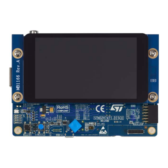
The STM32H747I-DISCO Discovery kit, shown in
Figure 1
and
Figure
2, is used as a
reference design for user application development before porting to the final product.
STM32H747I-DISC1, presented in
Figure
3, is the subset of STM32H747I-DISCO without
the LCD display module.
The full range of hardware features available on the board helps users improve application
development by an evaluation of all the peripherals (USB OTG2 HS, Ethernet, microSD™
card, SAI Audio DAC stereo with audio jack input and output, MEMS digital microphone,
®
SDRAM, Quad-SPI flash memory, DCMI connector, MIPI DSI
interface, and others).
®
ARDUINO
Uno V3 and Pmod™/STMod+ connectors provide easy connection to extension
shields or daughterboards for specific applications.
An STLINK-V3E is integrated into the board, as the embedded in-circuit debugger and
programmer for the STM32 MCU and the USB Virtual COM port bridge.
Figure 1. STM32H747I-DISCO top view
Figure 2. STM32H747I-DISCO bottom view
Figure 3. STM32H747I-DISC1 top view
Pictures are not contractual.
PCB colors may differ.
May 2023
UM2411 Rev 5
1/51
www.st.com
1
Advertisement
Table of Contents

Related Manuals for ST STM32H747I-DISCO


Summary of Contents for ST STM32H747I-DISCO
-
Page 1: Figure 1. Stm32H747I-Disco Top View
UM2411 User manual Discovery kit with STM32H747XI MCU Introduction The STM32H747I-DISCO Discovery kit is a complete demonstration and development ® ® platform for the STMicroelectronics Arm Cortex -M7 and -M4 dual-core-based STM32H747XIH6 microcontroller with four I C, six SPIs with two multiplexed full-duplex I interfaces, SDIO3.0, SDIO2.0, four USARTs, four UARTs, two FD-CANs, three 16-bit ADCs,... -
Page 2: Table Of Contents
5.6.2 STM32H747I-DISCO as USB host ......20 Ethernet ..........20 SDRAM . - Page 3 Product marking ..........43 STM32H747I-DISCO product history ......44 Board revision history .
- Page 4 Contents UM2411 Appendix A STMod+ GPIO sharing and multiplexing ..... 49 Revision history ........... . 50 4/51 UM2411 Rev 5...
- Page 5 STM32H747I-DISCO I/O assignment ........
- Page 6 STM32H747I-DISCO board layout (top view)........11...
-
Page 7: Features
Pmod™ expansion supported by Type 2A and Type 4A – STMod+ expansion – Audio daughterboard expansion • Flexible power-supply options: ST-LINK USB VBUS, USB OTG HS connector, or external sources • On-board STLINK-V3E debugger/programmer with USB re-enumeration capability: mass storage, Virtual COM port and debug port •... -
Page 8: Ordering Information
Ordering information UM2411 Ordering information To order the STM32H747I-DISCO or STM32H747I-DISC1 Discovery kit, refer to Table Additional information is available from the datasheet and reference manual of the target STM32. Table 1. List of available products Order code Board reference... -
Page 9: Development Environment
In particular, pay attention to the following component: ® • display MB1166 daughterboard in the CN15 connector if requested For product information related to the STM32H747XIH6 microcontroller, visit the www.st.com website. a. Windows is a trademark of the Microsoft group of companies. ® b. Linux is a registered trademark of Linus Torvalds. -
Page 10: Hardware Layout And Configuration
Hardware layout and configuration UM2411 Hardware layout and configuration The STM32H747I-DISCO Discovery kit is designed around the STM32H747XIH6 target microcontroller in TFBGA 240+25-pin package. Figure 4 illustrates the connections of the STM32H747XIH6 with the peripheral components. Figure 5 Figure 6 show the locations of the main components on the Discovery kit. -
Page 11: Figure 5. Stm32H747I-Disco Board Layout (Top View)
UM2411 Hardware layout and configuration Figure 5. STM32H747I-DISCO board layout (top view) USB OTG HS connector Camera module connector STLINK-V3E USB connector Ethernet connector (CN1) (P1) (CN2) (CN7) USB HS ® overcurrent LED STM32H747XI MCU ARDUINO connectors RCA connector (LD5) -
Page 12: Figure 6. Stm32H747I-Disco Board Layout (Bottom View)
Hardware layout and configuration UM2411 Figure 6. STM32H747I-DISCO board layout (bottom view) STMod+ STLINK-V3E ® COM LED connector LCD connector (LD10) (P2) (CN15) Joystick Reset Wake-up Pmod™ (B3) button button connector (B1) (B2) (P3) 4 color LEDs TAG connector MEMS microphone... -
Page 13: Figure 7. Stm32H747I-Disco Board Mechanical Dimensions (Top View)
UM2411 Hardware layout and configuration Figure 7 provides the mechanical dimensions of the STM32H747I-DISCO Discovery board. Figure 7. STM32H747I-DISCO board mechanical dimensions (top view) 88mm 77.84mm 5.08mm 37.7mm 16.81mm 48.26mm UM2411 Rev 5 13/51... -
Page 14: Stlink-V3E
Overview of ST-LINK derivatives technical note (TN1235) for details. Power supply The STM32H747I-DISCO Discovery kit is designed to be powered from a 5 V DC power source. One of the following five 5 V DC power inputs can be used, upon appropriate board configuration: •... -
Page 15: Supplying The Board Through Stlink-V3E Usb Port
5.2.1 Supplying the board through STLINK-V3E USB port To power the STM32H747I-DISCO in this way, the USB host (a PC) gets connected to the Micro-B USB receptacle of the STM32H747I-DISCO via a USB cable. The connection event starts the USB enumeration procedure. In its initial phase, the host USB port current supply capability is limited to 100 mA. -
Page 16: Smps/Ldo Power Supply
This causes an operating failure of STM32H747I-DISCO. The host PC is not capable of supplying 300 mA (the enumeration fails). The STLINK- V3E does not supply the rest of the STM32H747I-DISCO from its USB port VBUS line. 5.2.3 SMPS/LDO power supply There are two possible solutions to provide power to MCU Vcore: SMPS or LDO. -
Page 17: Table 3. Power-Supply Related Jumper And Solder Bridge Settings
UM2411 Hardware layout and configuration Table 3 details jumper and solder bridge settings used for the configuration of the power supply of STM32H747I-DISCO. Table 3. Power-supply related jumper and solder bridge settings Jumper / Solder bridge Setting Configuration Default setting. -
Page 18: Clock References
The main clock can also be generated using an internal RC oscillator. The X2 reference clock must be disconnected by removing resistor R73 when the internal RC clock is used. Reset Source The general reset of the STM32H747I-DISCO board is active low. The reset sources are: • Reset button B1 •... -
Page 19: Digital Microphone
USB PHY with the ULPI interface. USB OTG connector CN1 is of the Micro-AB type. 5.6.1 STM32H747I-DISCO as USB device The STM32H747I-DISCO board may work as USB device on CN1 in any power source configuration. If the board is supplied by an external power source from jumper JP4 set on UM2411 Rev 5... -
Page 20: Stm32H747I-Disco As Usb Host
When a USB device connection to the CN1 Micro-AB USB connector is detected, the STM32H747I-DISCO board starts behaving as USB host. It sources 5 V on the VBUS terminal of CN1 Micro-AB USB connector to power the USB device. For this to happen, the STM32H747XIH6 MCU sets the U2 power switch to the ON state via the USB PHY. -
Page 21: Sdram
Each LED is in light-emitting state for a low level of the corresponding port of the STM32H747XIH6 MCU. 5.12 Physical input devices The STM32H747I-DISCO board provides a number of input devices for physical human control: • Four-way joystick controller with select key (B3) •... -
Page 22: Connectors
Connectors UM2411 Connectors USB OTG HS Micro-AB connector CN1 An USB OTG high speed communication link is available at USB Micro-AB receptacle connector CN1. Micro-AB receptacle enables USB Host and USB Device features. Figure 8. USB OTG HS Micro-AB connector CN1 MSv46072V1 Table 6. -
Page 23: Stlink-V3E Usb Micro-B Connector Cn2
UM2411 Connectors STLINK-V3E USB Micro-B connector CN2 USB connector CN2 is used to connect the embedded STLINK-V3E to the PC for programming and debugging software. Figure 9. USB Micro-B connector CN2 MSv46073V1 Table 7. USB Micro-B connector CN2 Pin number Description Pin number Description... -
Page 24: Arduino ® Uno V3 Connectors Cn5, Cn6, Cn8 And Cn9
PD12 I2C4_SCL 1. The +3V3 on ARD connector Pin4 of CN8 is not a power input for STM32H747I-DISCO board, to simplify power architecture. 2. The external voltage applied to pin VIN on Pin8 of CN8 must be in the range 6 to 9V at 25°C ambient temperature. If a higher voltage is applied on the regulator U19, it may overheat and could be damaged. -
Page 25: Ethernet Rj45 Connector Cn7
A, yellow LED K, green LED A, green LED Audio blue jack (Line In) connector CN10 The 3.5 mm stereo audio blue jack input CN10 is available on the STM32H747I-DISCO Discovery board for audio line input. UM2411 Rev 5 25/51... -
Page 26: Audio Green Jack (Line Out) Connector Cn11
Connectors UM2411 Audio green jack (Line Out) connector CN11 The 3.5 mm stereo audio green jack output CN11 is available on the STM32H747I-DISCO Discovery board for headphones. Figure 11. Stereo headset with microphone jack CN11 MSv46080V1 Table 12. Audio jack connector CN11 (on board) -
Page 27: Microsd™ Card Connector Cn12
UM2411 Connectors microSD™ card connector CN12 microSD™ cards with 4 Gbytes or more capacity are inserted in the receptacle CN12. Four data bits of the SDMMC1 interface, CLK and CMD signals of the STM32H747XIH6 are used to communicate with the microSD™ card at +3V3 only. The card insertion is detected by the PI8 GPIO: when a microSD™... -
Page 28: Stdc14 Connector Cn13
Connectors UM2411 6.10 STDC14 connector CN13 Figure 13. STDC14 debugging connector CN13 (top view) MSv51224V1 Table 14. STDC14 debugging connector CN13 Terminal Function / MCU port Terminal Function / MCU port SWDIO/TMS (PA13) SWDCLK/TCK (PA14) SWO/TDO (PB3) TDI (PA15) RESET# VCP_RX (PA10) VCP_TX (PA9) 28/51... -
Page 29: External 5 V Usb Micro-B Connector Cn14
LCD connector CN15 (MIPI ® The CN15 connector is designed to connect the DSI LCD daughterboard. The MB1166 daughterboard is available to be mounted on the STM32H747I-DISCO board. Table 16 shows the assignment of CN15 and STM32H747XIH6 terminals. ® Figure 15. DSI... -
Page 30: Table 16. Dsi ® Lcd Module Connector Cn15
Connectors UM2411 ® Table 16. DSI LCD module connector CN15 CN15 pin Function Function connection number connection DSI_CK_P DSI_INT DSI_CK_N DSI_D0_P DSI_D0_N DSI_D1_P DSI_D1_N BLVDD (5V) BLVDD (5V) BLGND BLGND SCLK/MCLK 3.3 V LRCLK I2S_DATA PD13 I2C_SDA PD12 I2C_SCL CEC_CLK DSI_TE DSI_BL_CTRL PJ12... -
Page 31: Tag Connector Cn16
UM2411 Connectors 6.13 TAG connector CN16 The TAG connector footprint CN16 is used to connect STM32H747XIH6 microcontroller for programming or debugging the board. Figure 16. TAG connector CN16 Table 17. TAG connector CN16 Pin number Description Pin number Description SWDIO/TMS (PA13) SWDCLK/TCK (PA14) SWO/TDO (PB3) TDI (PA15) -
Page 32: Camera Module Connector P1
P1. The reference of the camera module to be used is STM32F4DIS-CAM. This module must be connected with caution before powering the STM32H747I-DISCO Discovery board. The camera module I²C addresses are 0x61 and 0x60. The camera is usable by default. -
Page 33: Stmod+ Connector P2
The standard 20-pin STMod+ connector is available on the STM32H747I-DISCO board to increase the compatibility with external boards and modules from the microcontrollers ecosystem. By default, it is designed to support an ST dedicated fan-out board, which allows connecting different modules or board extensions from different manufacturers. The fan-out board also embeds a 3V3 regulator. -
Page 34: Pmod™ Connector P3
6.17 Pmod™ connector P3 The standard 12-pin Pmod™ connector is available on the STM32H747I-DISCO Discovery board to support low frequency, low I/O pin count peripheral modules. The Pmod™ interface implemented on the STM32H747I-DISCO Discovery board is compatible with the Pmod™... -
Page 35: Stm32H747I-Disco I/O Assignment
UM2411 STM32H747I-DISCO I/O assignment STM32H747I-DISCO I/O assignment Table 22. STM32H747I-DISCO I/O assignment GPIO port GPIO primary interface QSPI_BK2_IO2 PMOD#2- USART2_TX PMOD#4- USART2_RTS PC10 SDIO1_D2 PA15 JTDI FMC_D25 FMC_D24 FMC_D28 FMC_NBL3 FMC_NBL2 ULPI_D7 VDDLDO VCAP JOY_RIGHT PG10 DCMI_D2 VBAT PJ15 Audio_INT... - Page 36 STM32H747I-DISCO I/O assignment UM2411 Table 22. STM32H747I-DISCO I/O assignment (continued) GPIO port GPIO primary interface JOY_LEFT PG11 ETH_/TX_EN/TX_EN PC15-OSC32_OUT OSC32_OUT SPDIF_RX0 PC12 SDIO1_CK FMC_D27 PA13 JTMS-SWDIO VDDLDO PC14-OSC32_IN OSC32_IN ETH_nINT || SAI4_CK1 FMC_NBL0 DCMI_VSYNC JTDO/TRACESWO JOY_UP JOY_DOWN PG12 ETH_/TXD1/TXD1 SAI1_SCK_A...
- Page 37 UM2411 STM32H747I-DISCO I/O assignment Table 22. STM32H747I-DISCO I/O assignment (continued) GPIO port GPIO primary interface PG13 ETH_/TXD0/TXD0 VLXSMPS PJ13 PMOD#12_GPIO FMC_D3 SDIO1_D0 SDIO1_D1 || DCMI_D3 CEC_CK || MCO1 PA12 PMOD#4-SPI2_SCK/2_CK PA11 PMOD#1-SPI2_NSS/2_WS FMC_D30 PC13 TAMP_1/WKUP2 uSD_Detect SAI1_SD_A PDR_ON BOOT0 VDDSMPS...
- Page 38 STM32H747I-DISCO I/O assignment UM2411 Table 22. STM32H747I-DISCO I/O assignment (continued) GPIO port GPIO primary interface VDD50USB VFBSMPS FMC_A1 FMC_A0 PI12 LED1 FMC_BA0 DSI_Reset FMC_A12 JOY_SEL PI13 LED2 PI14 LED3 FMC_A3 PH1 - OSC_OUT OSC_OUT ARD_D13-SPI5_SCK ARD_D10-SPI5_NSS || TIM1_CH1 PH0 - OSC_IN...
- Page 39 UM2411 STM32H747I-DISCO I/O assignment Table 22. STM32H747I-DISCO I/O assignment (continued) GPIO port GPIO primary interface NRST NRST PJ11 ARD_D12-SPI5_MISO VSSDSI DSI_D1P DSI_D1N QSPI_BK1_IO3 QSPI_BK1_IO2 PMOD#14_PWM || ARD_D3-TIM13_CH1 VDDA PJ10 ARD_D11-SPI5_MOSI || TIM1_CH2N VSSDSI DSI_CKP DSI_CKN ULPI_STP PF10 ARD_A1 QSPI_BK1_IO1 VREF+...
- Page 40 STM32H747I-DISCO I/O assignment UM2411 Table 22. STM32H747I-DISCO I/O assignment (continued) GPIO port GPIO primary interface ARD_D0-UART8_RX VSSDSI DSI_D0P DSI_D0N ETH_MDC || SAI4_D1 PMOD#3-SPI2_MISO/2_SDI PMOD#2-SPI2_MOSI/2_SDO VREF- ARD_D1-UART8_TX ARD_D6-TIM8_CH2N ARD_D9-TIM8_CH2 VCAPDSI QSPI_BK2_IO0 ETH_MDIO ETH_/RX_CLK/REF_CLK/CLK PMOD#1- USART2_CTS_NSS ARD_D7 PE10 FMC_D7 VSSA PE11 FMC_D8...
- Page 41 UM2411 STM32H747I-DISCO I/O assignment Table 22. STM32H747I-DISCO I/O assignment (continued) GPIO port GPIO primary interface ULPI_NXT FMC_SDNWE PI15 LED4 OTG_HS_OverCurrent PF13 FMC_A7 PF14 FMC_A8 FMC_D6 PC2_C ARD_A4 PE12 FMC_D9 PE15 FMC_D12 ARD_D8 FMC_D17 PH12 FMC_D20 PD11 QSPI_BK1_IO0 PD12 PMOD#7/ARD_D15-I2C4_SCL PD13...
- Page 42 STM32H747I-DISCO I/O assignment UM2411 Table 22. STM32H747I-DISCO I/O assignment (continued) GPIO port GPIO primary interface ETH_/RXD0/RXD0/RXD ULPI_D2 DSI_TE PF11 FMC_SDNRAS FMC_A10 FMC_D5 PE14 FMC_D11 VCAP1 VDDLDO FMC_SDCKE1 PB13 ULPI_D6 PB14 PMOD#9-SPI2_MISO/2_SDI FMC_D13 ULPI_D0 PMOD#13_ADC || ARD_A0 || DCMI_HSYNC ETH_/RXD1/RXD1 ULPI_D1...
-
Page 43: Stm32H747I-Disco Discovery Kit Information
Parts marked as "ES" or "E" are not yet qualified and therefore not approved for use in production. ST is not responsible for any consequences resulting from such use. In no event will ST be liable for the customer using any of these engineering samples in production. -
Page 44: Stm32H747I-Disco Product History
STM32H747I-DISCO Discovery kit information UM2411 STM32H747I-DISCO product history Table 23. Product history Order Product Product change Product details Product limitations code identification description MCU: – 32H747XIH6M$x7 revision "V" MCU errata sheet: – STM32H745/747xI/G and STM32H755/757xI 32H747IDISC1/ device limitations Initial revision... - Page 45 UM2411 STM32H747I-DISCO Discovery kit information Table 23. Product history (continued) Order Product Product change Product details Product limitations code identification description MCU: – 32H747XIH6M$x7 revision "V" MCU errata sheet: – STM32H745/747xI/G and STM32H755/757xI device limitations SB30 closed by default on...
-
Page 46: Board Revision History
STM32H747I-DISCO Discovery kit information UM2411 Board revision history Table 24. Board revision history Board variant and Board change Board reference Board limitations revision description DEFAULT-A03 Initial revision No limitation LCD FRIDA FRD397B25009-D-CTK is DEFAULT-A09 No limitation replaced by FRIDA MB1166 FRD400B25025-A-CTK. -
Page 47: Federal Communications Commission (Fcc) And Ised Canada Compliance Statements
UM2411 Federal Communications Commission (FCC) and ISED Canada Compliance Statements Federal Communications Commission (FCC) and ISED Canada Compliance Statements FCC Compliance Statement 9.1.1 Part 15.19 This device complies with Part 15 of the FCC Rules. Operation is subject to the following two conditions: (1) this device may not cause harmful interference, and (2) this device must accept any interference received, including interference that may cause undesired operation. -
Page 48: Ce Conformity
CE conformity UM2411 CE conformity 10.1 Warning EN 55032 / CISPR32 (2012) Class A product Warning: This device is compliant with Class A of EN55032 / CISPR32. In a residential environment, this equipment may cause radio interference. Avertissement : cet équipement est conforme à la Classe A de la EN55032 / CISPR 32. Dans un environnement résidentiel, cet équipement peut créer des interférences radio. -
Page 49: Table 25. Stmod+ Gpio Sharing And Multiplexing
Appendix A STMod+ GPIO sharing and multiplexing Table 25. STMod+ GPIO sharing and multiplexing Shared or exclusive functions STMod+ Shared or exclusive functions DFSDM Pmod™ Some other Alternate Functions Basic Port Pins Port Basic Some other Alternate Functions Pmod™ DFSDM DCMI CTSS2 ADC123_INO, TIM5_CH1... -
Page 50: Table 26. Document Revision History
Table 5: Ethernet related solder bridge and resistor settings. 3-Jan-2020 Updated Section 5.2.3: SMPS/LDO power supply with hardware/firmware mismatch deadlock recovery. Added Chapter 8: STM32H747I-DISCO Discovery kit information including Section 8.2: STM32H747I-DISCO product history. Added Chapter 9: Federal Communications Commission (FCC) and ISED Canada Compliance... - Page 51 ST products and/or to this document at any time without notice. Purchasers should obtain the latest relevant information on ST products before placing orders. ST products are sold pursuant to ST’s terms and conditions of sale in place at the time of order acknowledgment.
Need help?
Do you have a question about the STM32H747I-DISCO and is the answer not in the manual?
Questions and answers