Table of Contents
Advertisement
Discovery kits with STM32H745XI and STM32H750XB microcontrollers
Introduction
The
STM32H745I-DISCO
and
®
for STMicroelectronics Arm
STM32H750XB
(STM32H750XBH6 order code) microcontrollers. Both devices feature four I
2
simplex I
Ss, two SD/SDIO/DMMC interfaces, four USARTs, four UARTs, one LPUART, two CAN controllers, three 16-bit ADCs,
two 12-bit DACs, four SAIs, 8- to 14-bit digital camera interface, 1 Mbyte (STM32H745XIH6) or 128 Kbytes (STM32H750XBH6)
of internal SRAM and 2 Mbytes of Flash memory, a USB OTG HS and a USB OTG FS, an Ethernet MAC interface, an FMC
interface, a Quad-SPI interface, and SWD debugging support. The
enable users to quickly get started and develop applications.
In addition, the
STM32H745I-DISCO
for user application prototyping before porting to the final product.
The full range of hardware features available on the board helps users improve application development by an evaluation
of almost all peripherals (such as USB OTG FS, Ethernet 10/100Mb/s, eMMC, USART, SAI Audio DAC stereo with audio
jack input and output, MEMS digital microphone, SDRAM, Quad-SPI Flash memory, and RGB LCD interface with capacitive
multi-touch panel). ARDUINO
applications.
STLINK-V3E is integrated into the board, as an embedded in-circuit debugger and programmer for the STM32 microcontroller
and the USB Virtual COM port bridge.
The
STM32H745I-DISCO
and
STM32 comprehensive software HAL library as well as various software examples.
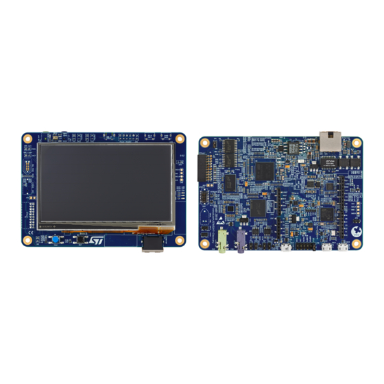
Figure 1.
STM32H745I-DISCO and STM32H750B-DK
boards (top view)
Pictures are not contractual. PCB colors may differ.
UM2488 - Rev 8 - September 2021
For further information contact your local STMicroelectronics sales office.
STM32H750B-DK
Discovery kits are complete demonstration and development platforms
®
Cortex
-M7 and -M4 dual-core-based
and STM32H750B-DK, shown in
®
Uno V3 connectors provide easy connection to extension shields or daughterboards for specific
STM32H750B-DK
boards come with the STM32CubeH7 MCU package, which provides an
STM32H745XI
(STM32H745XIH6 order code) and
2
Cs, six SPIs with three multiplexed
STM32H745I-DISCO
and
STM32H750B-DK
Figure 1
and
Figure
2, can be used as a reference design
Figure 2.
STM32H745I-DISCO and STM32H750B-DK
boards (bottom view)
UM2488
User manual
Discovery kits
www.st.com
Advertisement
Table of Contents

Related Manuals for ST STM32H745I-DISCO


Summary of Contents for ST STM32H745I-DISCO
-
Page 1: Figure 1. Stm32H745I-Disco And Stm32H750B-Dk Boards (Top View)
STM32H745I-DISCO STM32H750B-DK boards come with the STM32CubeH7 MCU package, which provides an STM32 comprehensive software HAL library as well as various software examples. Figure 1. STM32H745I-DISCO and STM32H750B-DK Figure 2. STM32H745I-DISCO and STM32H750B-DK boards (top view) boards (bottom view) Pictures are not contractual. PCB colors may differ. -
Page 2: Features
4.3” RGB interface LCD with touch panel connector • Ethernet compliant with IEEE-802.3-2002, and PoE • USB OTG FS with Micro-AB connector • SAI audio codec • One ST-MEMS digital microphone • 2× 512-Mbit Quad-SPI NOR Flash memory • 128-Mbit SDRAM • 4-Gbyte on-board eMMC •... -
Page 3: Ordering Information
STM32H750XBH6 Codification The codification composition is detailed in Table Table 2. Codification explanation STM32H7XXY-DISCO Description Example: STM32H745I-DISCO STM32H7XXY-DK STM32H7 MCU series in STM32 32-bit Arm Cortex MCUs STM32H7 Series MCU product line in the series STM32H745 STM32 Flash memory size: •... -
Page 4: Development Environment
STM32 Flash memory for easy demonstration of the device peripherals in standalone mode. The latest versions of the demonstration source code and associated documentation can be downloaded from www.st.com. UM2488 - Rev 8 page 4/39... -
Page 5: Conventions
UM2488 Conventions Conventions Table 3 provides the conventions used for the ON and OFF settings in the present document. Table 3. ON/OFF convention Convention Definition Jumper JPx ON Jumper fitted Jumper JPx OFF Jumper not fitted Jumper JPx [1-2] Jumper fitted between Pin 1 and Pin 2 Solder bridge SBx ON SBx connections closed by 0 Ω... -
Page 6: Delivery Recommendations
UM2488 Delivery recommendations Delivery recommendations Before first use, check the board for any damage that might have occurred during shipment, that all socketed components are firmly fixed in their sockets and that none are loose in the plastic bag. UM2488 - Rev 8 page 6/39... -
Page 7: Hardware Layout And Configuration
3) illustrates the connection between the microcontroller and the peripherals (SDRAM, eMMC, Quad-SPI Flash memory, CAN FD (FDCAN), LCD RGB connector, USB OTG connectors, ® UART, Ethernet, Audio, TAG connector, STDC connector, ARDUINO Uno shields and embedded ST-LINK). Figure 4 Figure 5 help to locate these features on the... -
Page 8: Stm32H753I-Eval Evaluation Board Layout
UM2488 STM32H745I-DISCO and STM32H750B-DK layout STM32H745I-DISCO and STM32H750B-DK layout Figure 4. STM32H745I-DISCO and STM32H750B-DK Discovery board top layout STMod+ connector TAG connector (P1) (CN16) User button MEMS microphone (B1) (U34) Reset button (B2) RGB LCD connector (U33) Power header (JP8) -
Page 9: Figure 5. Stm32H745I-Disco And Stm32H750B-Dk Discovery Board Bottom Layout
UM2488 STM32H745I-DISCO and STM32H750B-DK layout Figure 5. STM32H745I-DISCO and STM32H750B-DK Discovery board bottom layout ARDUINO ® connectors (CN2, CN6) USB power connector (CN15) Ethernet connector (CN1) STLK USB connector (CN14) Power header (JP8) USB OTG FS connector (CN13) ARDUINO ®... -
Page 10: Stm32H753I-Eval Evaluation Board Mechanical Drawing
Figure 6 shows the mechanical dimensions of the STM32H745I-DISCO STM32H750B-DK boards. Figure 6. STM32H745I-DISCO and STM32H750B-DK Discovery board mechanical drawing (bottom view) Embedded STLINK-V3E The STLINK-V3E programming and debugging tool is integrated into the STM32H745I-DISCO STM32H750B-DK Discovery kits. It supports: •... -
Page 11: Power Supply
The STLINK-V3E requires drivers to be installed on Windows . It embeds a firmware that needs to be updated from time to time in order to benefit from new functionalities and bug corrections. Refer to technical note Overview of ST-LINK derivatives (TN1235) for details. Power supply STM32H745I-DISCO... - Page 12 A deadlock occurs if the STM32H745I-DISCO SMPS/LDO firmware PWR configuration does not match the board hardware configuration: after the reset, the ST-LINK cannot connect the target anymore. The firmware PWR configuration must be set as follows in function SystemClock_Config in file main.c: •...
-
Page 13: Clock Sources
Table 4. Power-supply related jumper and solder bridge settings describes the settings of all the jumpers related to the powering of the STM32H745I-DISCO/STM32H750B-DK and the extension board. VDD_MCU corresponds to the STM32H745XIH6/STM32H750XBH6 digital supply voltage line. It can be connected to a fixed 3.3 V supply. -
Page 14: Reset Sources
Two external speakers can be connected to WM8994ECS/R via CN18 for left speaker and CN17 for right speaker. • STM32H745I-DISCO STM32H750B-DK feature one digital MP34DT01TR microphones (ST MEMs microphone). They are connected to the input digital microphones of the STM32H745XIH6/ STM32H750XBH6 and are managed by the PDM functionality. USB OTG_FS STM32H745I-DISCO... -
Page 15: Power Over Ethernet
This module is an IEEE802.3af compliant class 1 / 2 PoE converter, based on a simple diode rectified Flyback topology built around ST PM8800A component. This “powered device” module accepts a 48 V input voltage and can deliver 5 V with 600 mA. -
Page 16: Buttons And Leds
The black button (B2), located on the board top side, is the reset of the STM32H745XIH6 and STM32H750XBH6 microcontrollers. Refer to Figure 4. STM32H745I-DISCO and STM32H750B-DK Discovery board top layout. The blue button (B1), located on the top side, is available to be used as a digital input or as Wakeup alternate function. -
Page 17: Connectors
ARDUINO Uno V3 connectors ® CN2, CN3, CN6 and CN7 are female connectors compatible with the ARDUINO standard. Most shields ® designed for ARDUINO can fit to the STM32H745I-DISCO STM32H750B-DK Discovery kits. The ® ® STM32H745I-DISCO/STM32H750B-DK ARDUINO connectors support ARDUINO Uno V3. -
Page 18: Cn13 Usb Otg_Fs Micro-Ab Connector
UM2488 CN13 USB OTG_FS Micro-AB connector CN13 USB OTG_FS Micro-AB connector Figure 7. CN13 USB OTG Micro-AB connector (front view) Table 8. CN13 USB OTGFS micro-AB connector Pin number Description Pin number Description VBUS CN1 Ethernet RJ45 connector Figure 8. CN1 Ethernet RJ45 connector (front view) Table 9. -
Page 19: Lcd Rgb Connector
UM2488 LCD RGB connector LCD RGB connector Figure 9. LCD RGB connector (footprint) Table 10. LCD RGB connector Description Pin connection Pin number Description Pin connection LCD_BL_K LCD_BL_A LCD_R0 PI15 LCD_R1 LCD_R2 LCD_R3 LCD_R4 LCD_R5 LCD_R6 LCD_R7 LCD_G0 LCD_G1 LCD_G2 LCD_G3 PJ10 LCD_G4... -
Page 20: Cn2 Stmod+ Connector
UM2488 CN2 STMod+ connector CN2 STMod+ connector An STMod+ connector is available on the STM32H745I-DISCO STM32H750B-DK Discovery kits. It provides flexibility in small form factor applications. In addition, the STMod+ connector expands the SPI interface and frees I/Os that can be used by other peripheral expansions. -
Page 21: Cn8 Audio Line Input (Blue Jack) Connector
UM2488 CN8 audio line input (blue jack) connector CN8 audio line input (blue jack) connector A 3.5 mm stereo audio green jack input, CN8, can support the audio line input. 7.10 CN16 TAG connector The CN16 TAG connector is used to connect the STM32H745XIH6/STM32H750XBH6 microcontroller for the board programming and debugging. -
Page 22: Cn15 Usb Power Connector
UM2488 CN15 USB power connector 7.12 CN15 USB power connector Figure 12. CN15 USB Micro-B connector (front view) Table 15. CN15 USB Micro-B connector Pin number Description Pin number Description VBUS UM2488 - Rev 8 page 22/39... -
Page 23: Stm32H745I-Disco And Stm32H750B-Dk I/O Assignment
UM2488 STM32H745I-DISCO and STM32H750B-DK I/O assignment STM32H745I-DISCO and STM32H750B-DK I/O assignment Table 16. STM32H745I-DISCO and STM32H750B-DK I/O assignment Pin name Pin number Signal or label Comment STMOD#1-CTS MII_RX_CLK MII_MDIO STMOD#14-PWM STMOD#13-ADC OTG_FS2_PSO ARD_D3 MII_RX_DV ARD_D5 VBUS_FS2 PA10 USB_OTG_FS2_ID PA11 USB_OTG_FS2_N... - Page 24 UM2488 STM32H745I-DISCO and STM32H750B-DK I/O assignment Pin name Pin number Signal or label Comment MII_RXD1 SDIO1_D6 SDIO1_D7 SDIO1_D0 SDIO1_D1 PC10 SDIO1_D2 PC11 SDIO1_D3 PC12 SDIO1_CK PC13 WAKEUP PC14 OSC32_IN PC15 OSC32_OUT SDRAM_D2 SDRAM_D3 SDIO1_CMD ARD_D13 STMOD#4-RTS STMOD#2-TX STMOD#3-RX LCD_DISP SDRAM_D13...
- Page 25 UM2488 STM32H745I-DISCO and STM32H750B-DK I/O assignment Pin name Pin number Signal or label Comment PE14 SDRAM_D11 PE15 SDRAM_D12 SDRAM_A0 SDRAM_A1 SDRAM_A2 SDRAM_A3 SDRAM_A4 SDRAM_A5 QSPI_BK1_IO3 QSPI_BK1_IO2 ARD_A1 QSPI_BK1_IO1 PF10 QSPI_CLK PF11 SDRAM_SDNRAS PF12 SDRAM_A6 PF13 SDRAM_A7 PF14 SDRAM_A8 PF15 SDRAM_A9...
- Page 26 UM2488 STM32H745I-DISCO and STM32H750B-DK I/O assignment Pin name Pin number Signal or label Comment SDRAM_SDCKE1 STMOD#20 LCD_R3 PH10 STMOD#12-RST PH11 OTG_FS2_Overcurrent PH12 STMOD#11-INT PH13 FDCAN1_TX PH14 FDCAN1_RX PH15 ARD_D9 LCD_G5 LCD_G6 ARD_D12 STMOD#8-MOSIs SAI2_MCLKA SAI2_SCKA SAI2_SDA SAI2_FSA ARD_D7 LCD_VSYNC PI10...
- Page 27 UM2488 STM32H745I-DISCO and STM32H750B-DK I/O assignment Pin name Pin number Signal or label Comment LCD_BL ARD_D4 LCD_G7 LCD_B4 LCD_B5 LCD_B6 LCD_B7 LCD_DE DSI_CK_P DSI_CK_N DSI_D0_P DSI_D0_N DSI_D1_P DSI_D1_N ARD_A2 ARD_A3 ARD_A4 ARD_A5 ARD_D7 EXT_RST ARD_A0 DSIHOST_TE VDDIO_SD1 VSSIO_SD VCAP1 VCAP2...
- Page 28 UM2488 STM32H745I-DISCO and STM32H750B-DK I/O assignment Pin name Pin number Signal or label Comment VCAP3 VDDIO1 VDDIO2 VDDIO33_LDO1 VDDIO33_LDO2 VDDIO33_LDO3 VDD50_USB VDD_USB33 VDDA VREF+ VBAT UM2488 - Rev 8 page 28/39...
- Page 29 UM2488 STM32H745I-DISCO and STM32H750B-DK I/O assignment Pin name Pin number Signal or label Comment VSSA VREF- VDD33_DSI VDD12_DSI_CAP VSSDSI1 VSSDSI2 VSSDSI3 VSSDSI4 VSSDSI5 1. For 10 Mbps half-duplex MII communication, SB3 and SB4 must be ON. UM2488 - Rev 8...
-
Page 30: Stm32H745I-Disco And Stm32H750B-Dk Product Information
Evaluation tools marked as “ES” or “E” are not yet qualified and therefore not ready to be used as reference design or in production. Any consequences deriving from such usage will not be at ST charge. In no event, ST will be liable for any customer usage of these engineering sample tools as reference designs or in production. -
Page 31: Board Revision History
UM2488 Board revision history Board revision history 9.4.1 Board MB1381 revision B-01 The revision B-01 is the initial release of master board MB1381. Product limitations No limitation identified for this board revision. UM2488 - Rev 8 page 31/39... -
Page 32: Appendix A Federal Communications Commission (Fcc) And Industry Canada (Ic)
UM2488 Federal Communications Commission (FCC) and Industry Canada (IC) Compliance Statements Appendix A Federal Communications Commission (FCC) and Industry Canada (IC) Compliance Statements FCC Compliance Statement Part 15.19 This device complies with Part 15 of the FCC Rules. Operation is subject to the following two conditions: (1) this device may not cause harmful interference, and (2) this device must accept any interference received, including interference that may cause undesired operation. -
Page 33: Appendix Bce Conformity
UM2488 CE conformity Appendix B CE conformity Warning EN 55032 / CISPR32 (2012) Class A product Warning: this device is compliant with Class A of EN55032 / CISPR32. In a residential environment, this equipment may cause radio interference. Avertissement : cet équipement est conforme à la Classe A de la EN55032 / CISPR 32. Dans un environnement résidentiel, cet équipement peut créer des interférences radio. -
Page 34: Revision History
Table 6. ARDUINO connectors (CN2, CN3, CN6, 12-Sep-2019 and CN7). Updated all schematics related to STM32H745I-DISCO in Section 9 Electrical schematics. Updated SMPS/LDO power supply in Section 6.4 Power supply for hardware/firmware mismatch 31-Jan-2020 deadlock recovery. -
Page 35: Table Of Contents
UM2488 Contents Contents Features................2 Ordering information . - Page 36 STM32H745I-DISCO product history ........
-
Page 37: List Of Tables
STM32H745I-DISCO and STM32H750B-DK I/O assignment ........ -
Page 38: List Of Figures
Figure 2. STM32H745I-DISCO and STM32H750B-DK boards (bottom view) ....... . 1 Figure 3. - Page 39 ST’s terms and conditions of sale in place at the time of order acknowledgement. Purchasers are solely responsible for the choice, selection, and use of ST products and ST assumes no liability for application assistance or the design of Purchasers’...
Need help?
Do you have a question about the STM32H745I-DISCO and is the answer not in the manual?
Questions and answers