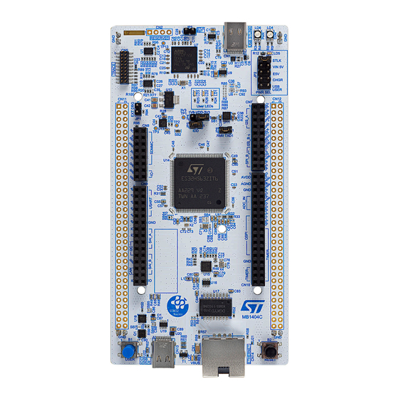
STM32 Nucleo open development platform with a wide choice of specialized shields. The STM32H5 Nucleo-144 board does not require any separate probe as it integrates the STLINK-V3EC debugger/ programmer. The STM32H5 Nucleo-144 board comes with the STM32 comprehensive free software libraries and examples available with the STM32CubeH5 MCU Package.
® – ST Zio connector including ARDUINO Uno V3 expansion connector – ST morpho extension pin headers for full access to all STM32 I/Os • Flexible power-supply options: ST-LINK USB V , USB connector, or external sources • On-board STLINK-V3EC debugger/programmer with USB re-enumeration capability: mass storage, Virtual COM port, and debug port •...
UM3115 Ordering information Ordering information To order the STM32H5 Nucleo-144 board, refer to Table 1. Additional information is available from the datasheet and reference manual of the target STM32. Table 1. Ordering information Order code Board reference Target STM32 NUCLEO-H563ZI...
UM3115 Development environment Development environment System requirements ® ® ® • Multi‑OS support: Windows 10, Linux 64-bit, or macOS ® ® • USB Type-A or USB Type-C to USB Type-C cable Note: ® macOS is a trademark of Apple Inc., registered in the U.S. and other countries and regions. ®...
UM3115 Conventions Conventions Table 3 provides the conventions used for the ON and OFF settings in the present document. Table 3. ON/OFF convention Convention Definition Jumper JPx ON Jumper fitted Jumper JPx OFF Jumper not fitted Jumper JPx [1-2] Jumper fitted between Pin 1 and Pin 2 Solder bridge SBx ON SBx connections closed by 0 Ω...
Power the board by connecting the STM32H5 Nucleo-144 board to a PC with a USB Type-A or USB Type- ® cable through the USB connector (CN1). As a result, the PWR green LED (LD5), the COM LED (LD4), and the PWR LED (LD6) light up, while the three user LEDs (LD1 to LD3) blink.
UM3115 Hardware layout and configuration Hardware layout and configuration The STM32H5 Nucleo-144 board is designed around an STM32H5 series microcontroller in a 144-pin LQFP package. Figure 3 shows the connections between the STM32H5 and its peripherals (STLINK-V3EC, push-buttons, LEDs, USB, Ethernet, ST Zio connectors, and ST morpho headers).
UM3115 STM32H5 Nucleo-144 board layout STM32H5 Nucleo-144 board layout Figure 4. STM32H5 Nucleo-144 board top layout ® ST-LINK RST (JP3) ST-LINK USB Type-C connector (CN1) ST-LINK power status LED (LD6) ST-LINK COM LED (LD4) Power LED (LD5) (green) MIPI20 connector (CN5)
Overvoltage protection (U2) with current limitation Two tricolor LEDs (green, orange, and red) provide information about STLINK-V3EC communication status (LD4) and STLINK-V3EC power status (LD6). For detailed information about the management of these LEDs, refer to the technical note Overview of ST-LINK derivatives (TN1235). Drivers ®...
UM3115 Embedded STLINK-V3EC Table 5 below explains the JP1 jumper setting. Table 5. JP1 configuration Jumper Definition Setting Comment An external debugger connected to the MIPI20 connector (CN5) can be used. The level shifter (U1) is in high ON [1-2] impedance (HZ).
Page 13
UM3115 Embedded STLINK-V3EC MIPI20 Designation Ground NRST Target NRST using SWD protocol or target JTMS (T_JTMS) using JTAG protocol TgtPwr 5 V target power to the target MCU–To be disconnected (SB84 OFF) TRACECLK Trace clock TgtPwr 5 V target power to the target MCU–To be disconnected (SB84 OFF) TRACED0 Trace Data0 Ground...
An external 3.3 V power supply (3V3) connected to CN8 pin 7 or CN11 pin 16 In case VIN, 5V_EXT, or 3V3 is used to power the STM32H5 Nucleo-144 board, this power source must comply with the EN-60950-1: 2006+A11/2009 standard and must be safety extra low voltage (SELV) with limited power capability.
[3-4] (VIN 5V). The STM32H5 Nucleo-144 board and its shield boards can be powered in three different ways from the VIN external power supply, depending on the used voltage. The three power sources are summarized in Table Table 7.
Power supply input from 5V_EXT (5 V, 1.3 A maximum) 5V_EXT External power supply input from a USB charger (5 V) When the STM32H5 Nucleo-144 board is power supplied by a USB charger on CN1 (refer to Figure 11 Table 9), the JP2 jumper must be set on [7-8] (CHGR).
External power supply input from the USB user connector (5 V, 3 A maximum) The STM32H5 Nucleo-144 board and shield can be powered from the USB user connector (CN13). To select the USB user power source, JP2 must be fitted on [9-10] 'USB USER' (refer to...
UM3115 External power supply input 3V3_EXT (3.3 V, 1.3 A maximum) External power supply input 3V3_EXT (3.3 V, 1.3 A maximum) In some cases, it might be interesting to use the 3V3 provided by a shield board (CN8 pin 7 or CN11 pin 16) directly as power input (refer to Figure 13 Table...
There are four ways to configure the pins corresponding to the high‑speed external clock (HSE): • MCO from STLINK-V3EC (default): The MCO output of ST-LINK is used as an input clock of the STM32H5. The MCO clock frequency cannot be changed. it is fixed at 8 MHz and connected to the PF0/PH0‑OSC_IN of the STM32H5 series microcontroller.
Orange ON communication failure Green PWR LED (LD5) The green LED (LD5) indicates that the +5 V power supply is available on the STM32H5 Nucleo-144. This source is available on CN8 pin 9 and CN11 pin 18. STLINK POWER STATUS LD6 The tricolor LED (LD6) provides information about the STLINK-V3EC target power.
MCU voltage selection 1V8/3V3 10.3 MCU voltage selection 1V8/3V3 The STM32H5 Nucleo-144 board offers the possibility to supply the STM32H5 microcontroller with 1.8 or 3.3 V. JP4 is used to select the VDD_MCU power level: • JP4 jumper must be fitted on [1-2] to supply the MCU with 3V3 •...
UM3115 USB Type-C® FS 10.6 ® USB Type-C The STM32H5 Nucleo-144 board supports USB full-speed (FS) communication. The USB connector (CN13) is a ® USB Type-C connector. ® The STM32H5 Nucleo-144 board supports the USB Type-C Sink mode only. A green LED (LD7) lights up when V is powered by a USB Host and the NUCLEO-H563ZI board works as a USB Device.
10.7 Ethernet The STM32H5 Nucleo-144 board supports 10M/100M Ethernet communication by a PHY LAN8742A-CZ-TR (U15) and RJ45 connector (CN14). Ethernet PHY is connected to the STM32H5 series microcontroller via the RMII interface. The PHY RMII_REF_CLK generates the 50 MHz clock for the STM32H5 series microcontroller.
UM3115 Solder bridges and jumpers Solder bridges and jumpers SBxx can be found on the top layer and SB1xx can be found on the bottom layer of the STM32H5 Nucleo-144 board Table 17. Solder bridge and jumper configuration Solder Bridge...
Page 25
RMII signals These pins are used as RMII signals and connected to Ethernet PHY. SB10 must be OFF. PB15 can be used as I2S_2_SD on ST Zio (pin 3 of CN7) if not used on the ST morpho. SB34 (PG11), SB36...
Page 26
PE6 is connected to the ST Zio connector (pin28 of CN10) and is used as TIMER_1_BKIN1 signal. SB68 must be OFF. SB71 (PE6) PE2 can be used as the trace signal if SB68 is OFF or as the SAI_A_SD signal on ST Zio connector (pin20 of CN9) if SB68 is ON. SB72 NRST of STM32H5 is connected to Ethernet PHY (U15).
Page 27
VDD_MCU is not connected to VDD (the MCU is not power supplied). 1. The default status is in bold. All the other solder bridges present on the STM32H5 Nucleo-144 board are used to configure several I/Os and power supply pins for compatibility of features and pinout with the target‑supported STM32H5.
UM3115 Board connectors Board connectors Several connectors are implemented on the STM32H5 Nucleo-144 board. 12.1 ® STLINK-V3EC USB Type-C connector (CN1) ® The USB Type-C connector (CN1) is used to connect the embedded STLINK-V3EC to the PC for programming and debugging purposes.
12.3 Ethernet RJ45 connector (CN14) The STM32H5 Nucleo-144 board supports 10 Mbps/100 Mbps Ethernet communication with the LAN8742A-CZ- TR PHY (U15) from MICROCHIP and integrated RJ45 connector (CN14). The Ethernet PHY is connected to the MCU via the RMII interface.
UM3115 Ethernet RJ45 connector (CN14) The X4 oscillator generates the 25 MHz clock for the PHY. The 50 MHz clock for the MCU (derived from the 25 MHz crystal oscillator) is provided by the RMII_REF_CLK of the PHY. Figure 16. Ethernet RJ45 connector (CN14) front view Green LED: Ethernet traffic Amber LED: Ethernet connection...
Expansion connectors 13.1 ST Zio connectors For all STM32H5 Nucleo-144 boards, Figure 17 shows the signals connected by default to the ST Zio connectors ® (CN7, CN8, CN9, and CN10), including the support of ARDUINO Uno V3. Figure 17. STM32H5 Nucleo-144 board CN7, CN8, CN9, and CN10 are female connectors on the top side and male connectors on the bottom side.
UM3115 ST Zio connectors ® To cope with ARDUINO Uno V3, apply the following modifications: • SB52 and SB57 must be ON • SB53 and SB60 must be OFF to connect I C on A4 (pin 9) and A5 (pin 11 of CN9).
UM3115 ST Zio connectors Table 23. Zio connector (CN9) pinout STM32 STM32 STM32 STM32 Signal name Signal name name function name function ADC12_INP3 USART_B_SCLK USART2 ADC12_INP10 USART_B_RX USART2 ADC12_INP13 USART_B_TX USART2 ADC12_INP5 USART_B_RTS USART2 PC2/ ADC12_INP12/ USART_B_CTS USART2 I2C1_SDA PF11/...
They are used to connect the STM32H5 Nucleo-144 board to an extension board or a prototype/wrapping board placed on the top of the ST morpho. All signals and power pins of the STM32H5 are available on the ST morpho connector. An oscilloscope, logical analyzer, or voltmeter can also probe this connector.
Page 35
5V_STLK is the 5 V power coming from the STLINK-V3EC USB connector that rises before and it rises before the +5 V rises on the board. PA13 and PA14 are shared with SWD signals connected to STLINK-V3EC. ST does not recommend using them as I/O pins.
B01. The second line shows the board serial number used for traceability. Parts marked as “ES” or “E” are not yet qualified and therefore not approved for use in production. ST is not responsible for any consequences resulting from such use. In no event will ST be liable for the customer using any of these engineering samples in production.
UM3115 Federal Communications Commission (FCC) and ISED Canada Compliance Statements Federal Communications Commission (FCC) and ISED Canada Compliance Statements 15.1 FCC Compliance Statement Part 15.19 This device complies with Part 15 of the FCC Rules. Operation is subject to the following two conditions: (1) this device may not cause harmful interference, and (2) this device must accept any interference received, including interference that may cause undesired operation.
STM32H5 Nucleo-144 board mechanical drawing (in millimeters) ....... . 10...
Page 43
ST’s terms and conditions of sale in place at the time of order acknowledgment. Purchasers are solely responsible for the choice, selection, and use of ST products and ST assumes no liability for application assistance or the design of purchasers’...
Need help?
Do you have a question about the STM32H5 Nucleo-144 and is the answer not in the manual?
Questions and answers