Table of Contents
Advertisement
Discovery kits with STM32H745XI and STM32H750XB microcontrollers
Introduction
The
STM32H745I-DISCO
and
®
STMicroelectronics Arm
Cortex
STM32H750XB
(STM32H750XBH6 order code) microcontrollers. Both devices feature four I
2
simplex I
Ss, two SD/SDIO/DMMC interfaces, four USARTs, four UARTs, one LPUART, two CAN controllers, three 16-bit ADCs,
two 12-bit DACs, four SAIs, 8- to 14-bit digital camera interface, 1 Mbyte (STM32H745XIH6) or 128 Kbytes (STM32H750XBH6)
of internal SRAM and 2 Mbytes of Flash memory, a USB OTG HS and a USB OTG FS, an Ethernet MAC interface, an FMC
interface, a Quad-SPI interface, and SWD debugging support. The
enable users to quickly get started and develop applications.
In addition, the
STM32H745I-DISCO
design for user application prototyping before porting to the final product.
The full range of hardware features available on the board helps users improve application development by an evaluation of
almost all peripherals (such as USB OTG FS, Ethernet 10/100Mb/s, eMMC, USART, SAI Audio DAC stereo with audio jack
input and output, MEMS digital microphone, SDRAM, Quad-SPI Flash memory, and RGB LCD interface with capacitive multi-
®
touch panel). ARDUINO
Uno V3 connectors provide easy connection to extension shields or daughterboards for specific
applications.
STLINK-V3E is integrated into the board, as an embedded in-circuit debugger and programmer for the STM32 microcontroller
and the USB Virtual COM port bridge.
The
STM32H745I-DISCO
and
STM32 comprehensive software HAL library as well as various software examples.
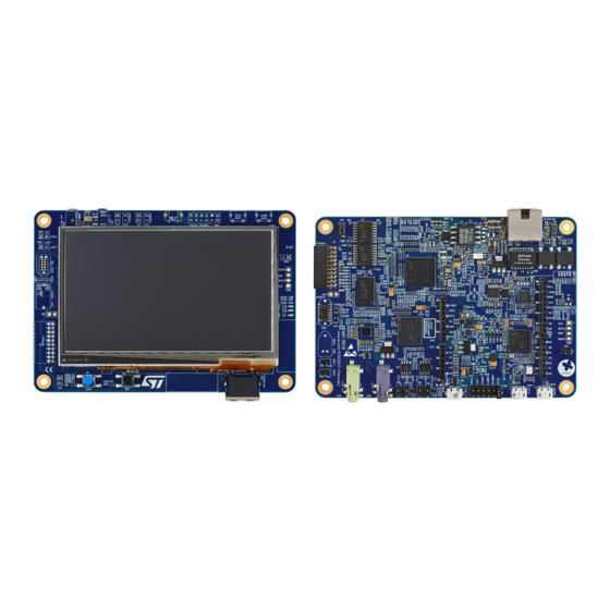
Figure 1.
STM32H745I-DISCO and STM32H750B-DK
boards (top view)
Pictures are not contractual. PCB colors may differ.
UM2488 - Rev 4 - September 2019
For further information contact your local STMicroelectronics sales office.
STM32H750B-DK
Discovery kits are complete demonstration and development platforms for
®
-M7 and -M4 dual-core-based
and STM32H750B-DK, shown in
STM32H750B-DK
boards come with the STM32CubeH7 MCU package, which provides an
STM32H745XI
(STM32H745XIH6 order code) and
2
STM32H745I-DISCO
and
Figure 1
and
Figure
2, can be used as a reference
Figure 2.
STM32H745I-DISCO and STM32H750B-DK
boards (bottom view)
UM2488
User manual
Cs, six SPIs with three multiplexed
STM32H750B-DK
Discovery kits
www.st.com
Advertisement
Table of Contents

Related Manuals for ST STM32H745I-DISCO


Summary of Contents for ST STM32H745I-DISCO
- Page 1 STM32H745I-DISCO STM32H750B-DK boards come with the STM32CubeH7 MCU package, which provides an STM32 comprehensive software HAL library as well as various software examples. Figure 1. STM32H745I-DISCO and STM32H750B-DK Figure 2. STM32H745I-DISCO and STM32H750B-DK boards (top view) boards (bottom view) Pictures are not contractual. PCB colors may differ.
-
Page 2: Features
4.3” RGB interface LCD with touch panel connector • Ethernet compliant with IEEE-802.3-2002, and PoE • USB OTG FS with Micro-AB connector • SAI audio codec • One ST-MEMS digital microphone • 2 x 512-Mbit Quad-SPI NOR Flash memory • 128-Mbit SDRAM • 4-Gbyte on-board eMMC •... -
Page 3: Ordering Information
Evaluation tools marked as “ES” or “E” are not yet qualified and therefore not ready to be used as reference design or in production. Any consequences deriving from such usage will not be at ST charge. In no event, ST will be liable for any customer usage of these engineering sample tools as reference design or in production. -
Page 4: Development Environment
STM32 Flash memory for easy demonstration of the device peripherals in standalone mode. The latest versions of the demonstration source code and associated documentation can be downloaded from www.st.com. UM2488 - Rev 4 page 4/55... -
Page 5: Conventions
UM2488 Conventions Conventions Table 3 provides the conventions used for the ON and OFF settings in the present document. Table 3. ON/OFF convention Convention Definition Jumper JPx ON Jumper fitted Jumper JPx OFF Jumper not fitted Jumper JPx [1-2] Jumper should be fitted between Pin 1 and Pin 2 Solder bridge SBx ON SBx connections closed by 0 Ω... -
Page 6: Delivery Recommendations
UM2488 Delivery recommendations Delivery recommendations Before the first use, make sure that no damage occurred to the board during shipment and no socketed components are not firmly fixed in their sockets or loose in the plastic bag. UM2488 - Rev 4 page 6/55... -
Page 7: Hardware Layout And Configuration
3) illustrates the connection between the microcontroller and the peripherals (SDRAM, eMMC, Quad-SPI Flash memory, FDCAN, LCD RGB connector, USB OTG connectors, UART, ® Ethernet, Audio, TAG connector, STDC connector, ARDUINO Uno shields and embedded ST-LINK). Figure 4 Figure 5 help to locate these features on the... - Page 8 UM2488 STM32H745I-DISCO and STM32H750B-DK layout STM32H745I-DISCO and STM32H750B-DK layout Figure 4. STM32H745I-DISCO and STM32H750B-DK Discovery board top layout P1 STMod+ CN16 TAG connector connector B1 reset button U34 MEMS microphone B2 user button U33 RGB LCD connector JP8 power header...
- Page 9 UM2488 STM32H745I-DISCO and STM32H750B-DK layout Figure 5. STM32H745I-DISCO and STM32H750B-DK Discovery board bottom layout CN12, CN16 Arduino connectors CN15 USB power connector CN14 STLK USB connector CN1 Ethernet connector JP8 power header CN3, CN7 Arduino connectors CN13 USB OTG_FS connector...
-
Page 10: Stm32H753I-Eval Evaluation Board Mechanical Drawing
Figure 6 shows the mechanical dimensions of the STM32H745I-DISCO STM32H750B-DK boards. Figure 6. STM32H745I-DISCO and STM32H750B-DK Discovery board mechanical drawing (bottom view) Embedded STLINK-V3E The STLINK-V3E programming and debugging tool is integrated into the STM32H745I-DISCO STM32H750B-DK Discovery kits. It supports: •... -
Page 11: Power Supply
The STLINK-V3E requires drivers to be installed on Windows . It embeds a firmware that needs to be updated from time to time in order to benefit from new functionalities and bug corrections. Refer to technical note Overview of ST-LINK derivatives (TN1235) for details. Power supply STM32H745I-DISCO... -
Page 12: Table 4. Power-Supply Related Jumper And Solder Bridge Settings
Resolder the solder bridge as described above for SMPS or LDO mode. At power-on, check that the ST-LINK operates normally. When the ST-LINK is connected, use the right SMPS/LDO configuration for your application. Table 4. Power-supply related jumper and solder bridge settings... -
Page 13: Clock Sources
UM2488 Clock sources Table 4. Power-supply related jumper and solder bridge settings Jumper/Solder bridge Setting Configuration STM32H745I-DISCO/STM32H750B-DK is supplied through the CN14 Micro-B USB receptacle. STM32H745I-DISCO/STM32H750B-DK is supplied through the pin 8 of CN3 (marked VIN). STM32H745I-DISCO/STM32H750B-DK is supplied through the RJ45 connector CN1. -
Page 14: Audio
This module is an IEEE802.3af compliant class 1 / 2 PoE converter, based on a simple diode rectified Flyback topology built around ST PM8800A component. This “powered device” module accepts a 48 V input voltage and can deliver 5 V with 600 mA. -
Page 15: Quad-Spi Nor Flash Memory
The black button (B2), located on the board top side, is the reset of the STM32H745XIH6 and STM32H750XBH6 microcontrollers. Refer to Figure 4. STM32H745I-DISCO and STM32H750B-DK Discovery board top layout. The blue button (B1), located on the top side, is available to be used as a digital input or as Wakeup alternate function. -
Page 16: Connectors
ARDUINO Uno V3 connectors ® CN2, CN3, CN6 and CN7 are female connectors compatible with the ARDUINO standard. Most shields ® designed for ARDUINO can fit to the STM32H745I-DISCO STM32H750B-DK Discovery kits. The ® ® STM32H745I-DISCO/STM32H750B-DK ARDUINO connectors support ARDUINO Uno V3. -
Page 17: Cn13 Usb Otg_Fs Micro-Ab Connector
UM2488 CN13 USB OTG_FS Micro-AB connector CN13 USB OTG_FS Micro-AB connector Figure 7. CN13 USB OTG Micro-AB connector (front view) Table 7. CN13 USB OTGFS micro-AB connector Pin number Description Pin number Description VBUS CN1 Ethernet RJ45 connector Figure 8. CN1 Ethernet RJ45 connector (front view) Table 8. -
Page 18: Lcd Rgb Connector
UM2488 LCD RGB connector LCD RGB connector Figure 9. LCD RGB connector (footprint) Table 9. LCD RGB connector Description Pin connection Pin number Description Pin connection LCD_BL_K LCD_BL_A LCD_R0 PI15 LCD_R1 LCD_R2 LCD_R3 LCD_R4 LCD_R5 LCD_R6 LCD_R7 LCD_G0 LCD_G1 LCD_G2 LCD_G3 PJ10 LCD_G4... -
Page 19: Cn2 Stmod+ Connector
UM2488 CN2 STMod+ connector CN2 STMod+ connector An STMod+ connector is available on the STM32H745I-DISCO STM32H750B-DK Discovery kits. It provides flexibility in small form factor applications. In addition, the STMod+ connector expands the SPI interface and frees I/Os that can be used by other peripheral expansions. -
Page 20: Cn8 Audio Line Input (Blue Jack) Connector
UM2488 CN8 audio line input (blue jack) connector CN8 audio line input (blue jack) connector A 3.5 mm stereo audio green jack input, CN8, can support the audio line input. 7.10 CN16 TAG connector The CN16 TAG connector is used to connect the STM32H745XIH6/STM32H750XBH6 microcontroller for the board programming and debugging. -
Page 21: Cn15 Usb Power Connector
UM2488 CN15 USB power connector 7.12 CN15 USB power connector Figure 12. CN15 USB Micro-B connector (front view) Table 14. CN15 USB Micro-B connector Pin number Description Pin number Description VBUS UM2488 - Rev 4 page 21/55... -
Page 22: Stm32H745I-Disco And Stm32H750B-Dk I/O Assignment
UM2488 STM32H745I-DISCO and STM32H750B-DK I/O assignment STM32H745I-DISCO and STM32H750B-DK I/O assignment Table 15. STM32H745I-DISCO and STM32H750B-DK I/O assignment Pin Name Pin Number Signal or Label Comment STMOD#1-CTS MII_RX_CLK MII_MDIO STMOD#14-PWM STMOD#13-ADC OTG_FS2_PSO ARD_D3 MII_RX_DV ARD_D5 VBUS_FS2 PA10 USB_OTG_FS2_ID PA11 USB_OTG_FS2_N... - Page 23 UM2488 STM32H745I-DISCO and STM32H750B-DK I/O assignment Pin Name Pin Number Signal or Label Comment MII_RXD1 SDIO1_D6 SDIO1_D7 SDIO1_D0 SDIO1_D1 PC10 SDIO1_D2 PC11 SDIO1_D3 PC12 SDIO1_CK PC13 WAKEUP PC14 OSC32_IN PC15 OSC32_OUT SDRAM_D2 SDRAM_D3 SDIO1_CMD ARD_D13 STMOD#4-RTS STMOD#2-TX STMOD#3-RX LCD_DISP SDRAM_D13...
- Page 24 UM2488 STM32H745I-DISCO and STM32H750B-DK I/O assignment Pin Name Pin Number Signal or Label Comment PE13 SDRAM_D10 PE14 SDRAM_D11 PE15 SDRAM_D12 SDRAM_A0 SDRAM_A1 SDRAM_A2 SDRAM_A3 SDRAM_A4 SDRAM_A5 QSPI_BK1_IO3 QSPI_BK1_IO2 ARD_A1 QSPI_BK1_IO1 PF10 QSPI_CLK PF11 SDRAM_SDNRAS PF12 SDRAM_A6 PF13 SDRAM_A7 PF14 SDRAM_A8...
- Page 25 UM2488 STM32H745I-DISCO and STM32H750B-DK I/O assignment Pin Name Pin Number Signal or Label Comment SDRAM_SDNWE SDRAM_SDNE1 SDRAM_SDCKE1 STMOD#20 LCD_R3 PH10 STMOD#12-RST PH11 OTG_FS2_Overcurrent PH12 STMOD#11-INT PH13 FDCAN1_TX PH14 FDCAN1_RX PH15 ARD_D9 LCD_G5 LCD_G6 ARD_D12 STMOD#8-MOSIs SAI2_MCLKA SAI2_SCKA SAI2_SDA SAI2_FSA ARD_D7...
- Page 26 UM2488 STM32H745I-DISCO and STM32H750B-DK I/O assignment Pin Name Pin Number Signal or Label Comment PJ13 LCD_B1 PJ14 LCD_B2 PJ15 LCD_B3 LCD_BL ARD_D4 LCD_G7 LCD_B4 LCD_B5 LCD_B6 LCD_B7 LCD_DE DSI_CK_P DSI_CK_N DSI_D0_P DSI_D0_N DSI_D1_P DSI_D1_N ARD_A2 ARD_A3 ARD_A4 ARD_A5 ARD_D7 EXT_RST...
- Page 27 UM2488 STM32H745I-DISCO and STM32H750B-DK I/O assignment Pin Name Pin Number Signal or Label Comment VSSIO_SD VCAP1 VCAP2 VCAP3 VDDIO1 VDDIO2 VDDIO33_LDO1 VDDIO33_LDO2 VDDIO33_LDO3 VDD50_USB VDD_USB33 VDDA VREF+ VBAT UM2488 - Rev 4 page 27/55...
- Page 28 UM2488 STM32H745I-DISCO and STM32H750B-DK I/O assignment Pin Name Pin Number Signal or Label Comment VSSA VREF- VDD33_DSI VDD12_DSI_CAP VSSDSI1 VSSDSI2 VSSDSI3 VSSDSI4 VSSDSI5 UM2488 - Rev 4 page 28/55...
-
Page 29: Electrical Schematics
UM2488 Electrical schematics Electrical schematics This section provides the design schematics for the STM32H745I-DISCO STM32H750B-DK Discovery boards: • Overall schematic for the STM32H745I-DISCO and STM32H750B-DK, see Figure 13 • STM32H45I microcontroller I/Os, see Figure 14 • STM32H50XB microcontroller I/Os, see Figure 15 •... - Page 30 Figure 13. STM32H745I-DISCO and STM32H750B-DK schematic (top view) STlink_V3E_PWR STlink_V3E_Module U_MCU STlink_V3E_PWR.SchDoc STlink_V3E_Module.SchDoc STM32 microcontroller IOs.SchDoc LCD4.3.SchDoc T_PWR_EXT T_PWR_EXT T_SWDIO SWDIO T_PWR_EN T_PWR_EN T_SWCLK SWCLK I2C4 LCD_I2C T_SWO T_NRST Audio T_SW_DIR T_JTDI T_JTDI Audio.SchDoc T_VCP_TX VCP_TX T_VCP_RX VCP_RX Audio Audio Audio_I2C TAG.SchDoc...
- Page 31 R229 ARD_D6 ARD_D5 220K ESDA7P60-1U1M C181 Capacitor close to MCU ARD_D5 100nF ARD_D4 ESDA7P60-1U1M ARD_D4 ARD_D3 ARD_D3 ARD_D2 Title: STM32 microcontroller IOs ARD_D2 Project: STM32H745I-Disco ARD_D1 ARD_D1 ARD_D0 Variant: H745XI ARD_D0 Revision: B 02 Reference: MB1381 Size: Date: 06-SEP-19 Sheet:...
- Page 32 R229 ARD_D6 ARD_D5 220K ESDA7P60-1U1M C181 Capacitor close to MCU ARD_D5 ARD_D4 ESDA7P60-1U1M 100nF ARD_D4 ARD_D3 ARD_D3 Title: STM32 microcontroller IOs ARD_D2 ARD_D2 Project: STM32H745I-Disco ARD_D1 ARD_D1 Variant: H750XB ARD_D0 ARD_D0 Revision: B 01 Reference: MB1381 Size: Date: 11-JUNE-18 Sheet:...
- Page 33 100nF 100nF 100nF 100nF 100nF 100nF 100nF VREF+ VDDA VDD_MCU 100nF 100nF 100nF 100nF 100nF 100nF 100nF 100nF 100nF 100nF 10uF 100nF 100nF Title: STM32 microcontroller Power Project: STM32H745I-Disco Variant: H745XI Revision: B 02 Reference: MB1381 Size: Date: 06-SEP-19 Sheet:...
- Page 34 100nF 100nF 100nF 100nF 100nF 100nF 100nF VREF+ VDDA VDD_MCU 100nF 100nF 100nF 100nF 100nF 100nF 100nF 100nF 100nF 100nF 10uF 100nF 100nF Title: STM32 microcontroller Power Project: STM32H745I-Disco Variant: H750XB Revision: B 01 Reference: MB1381 Size: Date: 11-JUNE-18 Sheet:...
- Page 35 R94 to enable the TXER function, and close SB22,SB28,open SB14,SB25 for LED2 Remove R94 and SB14 to enable nINT founction, and close SB14,SB25, open SB22,SB28 for LED2 Title: Ethernet Project: STM32H745I-Disco Variant: H745XI Revision: B 02 Reference: MB1381 Size:...
- Page 36 0R_0805 TS431AILT 510R STPS1H100A 0R47 470pF, 100V Title: Project: STM32H745I-Disco NOTE : The AGND is a dedicated plan. NOTE : this diode must be placed close the Variant: H745XI 1nF, 100V 0R_0805 Chassis The resistor 0 ohm must be very close to pin 9...
- Page 37 Shield Shield Shield Shield VBUS_FS2 PA11 USB_FS2_DM R219 PA12 USB_FS2_DP 330R PA10 USB_FS2_ID USBLC6-4SC6 GREEN I/O1 I/O4 VBUS I/O2 I/O3 R221 9013-SOT23 R220 Title: USB OTG FS Project: STM32H745I-Disco Variant: H745XI Revision: B 02 Reference: MB1381 Size: Date: 06-SEP-19 Sheet:...
- Page 38 CANH CANL PH14 FDCAN1_RX R224 120R C176 100nF ESDCAN02-2BWY C170 100nF MCP2562FDT-H/SN R223 PB13 CN10 FDCAN2_TX STBY CANH CANL FDCAN2_RX R222 120R C174 100nF ESDCAN02-2BWY Title: FDCAN Project: STM32H745I-Disco Variant: H745XI Revision: B 02 Reference: MB1381 Size: Date: 06-SEP-19 Sheet:...
- Page 39 VDDQ VSSQ 100nF VDDQ VSSQ C102 100nF VDDQ VSSQ 100nF VDDQ VSSQ 100nF VDDQ VSSQ 100nF VDDQ VSSQ 100nF 100nF 100nF 100nF Place close SDRAM Title: SDRAM Project: STM32H745I-Disco Variant: H745XI Revision: B 02 Reference: MB1381 Size: Date: 06-SEP-19 Sheet:...
- Page 40 R205 VDDIM C133 C131 VSSQ VSSQ eMMC_RSTn R206 eMMC_RSTn RSTn VSSQ PC12 VSSQ SDIO1_CK R200 VSSQ SDIO1_CMD R201 When change to THGBMDG5D1LBAIL, mount C131/C133 R203 Title: eMMC Project: STM32H745I-Disco Variant: H745XI Revision: B 02 Reference: MB1381 Size: Date: 06-SEP-19 Sheet:...
- Page 41 Twin Quad SPI Flash solutions: One Twin Quad SPI Fllash U2:MT25TL01GHBB8ESF-0SIT U1:NA R53/R62/R54/R56/R60/SB8/SB48 ON R14/R3/R2/R9,/SB2,/C15 OFF Two Quad SPI Fllash U1:MT25QL512ABB8ESF-0SIT U2:MT25QL512ABB8ESF-0SIT R14/R3/R2/R9,/SB2,/C15 ON R53/R62/R54/R56/R60/SB8/SB48 OFF Title: QSPI Project: STM32H745I-Disco Variant: H745XI Revision: B 02 Reference: MB1381 Size: Date: 06-SEP-19 Sheet:...
- Page 42 PJ14 PJ15 LCD_B3 LCD_B4 C104 LCD_B5 4.7uF BLGND BLGND BLGND 100nF LCD_B6 LCD_B7 Default I2C Address : 01110000 Backlight driver & PFC of LCD panel Title: LCD4.3 Project: STM32H745I-Disco Variant: H745XI Revision: B 02 Reference: MB1381 Size: Date: 06-SEP-19 Sheet:...
- Page 43 I/O2 I/O3 C148 IN1RN CN17 SPKOUTRN SPK Right IN2RP/VRXP SPKOUTRP SB32 IN2RN/DMICDAT2 CPCA C109 2.2uF CPCB C111 2.2uF CPVOUTN C110 2.2uF CPVOUTP SB39 MICBIAS1 SB37 Title: Audio Project: STM32H745I-Disco Variant: H745XI Revision: B 02 Reference: MB1381 Size: Date: 06-SEP-19 Sheet:...
- Page 44 SB12 STMOD#3-RX STMOD#14-PWM SB10 STMOD#4-SCK STMOD#4-RTS PD12 STMOD_SCL STMOD#17 PI11 STMOD#8-MOSIs STMOD#18 PB14 STMOD#9-MISOs STMOD#19 PD13 STMOD_SDA STMOD#20 ATOM FH200210C-12000 STMOD_SDA PD13 STMOD_I2C STMOD_SCL PD12 Title: STMod+ Project: STM32H745I-Disco Variant: H745XI Revision: B 02 Reference: MB1381 Size: Date: 06-SEP-19 Sheet:...
- Page 45 Only footprint with Cable: TC2050-IDC-NL R241 TDO/SWO PA15 R240 R239 TRST R238 RESET# Place this connector close to STDC, they will share the same ESD components Title: Project: STM32H745I-Disco Variant: H745XI Revision: B 02 Reference: MB1381 Size: Date: 06-SEP-19 Sheet:...
- Page 46 ARD_D1 TX/D1 USART1_TX PC2_C SB33 ARD_A4 RX/D0 ARD_D0 USART1_RX ADC3_IN0 Socket 6x1 PD13 SB34 Socket 8x1 I2C4_SDA ADC3_IN1 PC3_C SB35 ARD_A5 PD12 SB36 I2C4_SCL Title: Arduino Connector Project: STM32H745I-Disco Variant: H745XI Revision: B 02 Reference: MB1381 Size: Date: 06-SEP-19 Sheet:...
- Page 47 GNDDetect T_NRST R180 T_NRSTa 3V3_STLK STLK_VCP_TX R188 T_VCP_RX T_VCP_TX R184 STLK_VCP_RX T_NRST STLK_SWDIO 330R STDC14 T_SWDIO STLK_SWCLK Green T_SWCLK T_VCP_TX T_SWO T_VCP_RX Title: ST-LINK/V3E-SWD Module Project: STM32H745I-Disco Variant: H745XI ESDALC6V1W5 ESDALC6V1W5 Revision: B 02 Reference: MB1381 Size: Date: 06-SEP-19 Sheet:...
- Page 48 Figure 31. STLINK-V3E-SWD power module 3V3_STLK U16B ST-LINKV3E_SWD 3.3 Volts ST-LINK VBUS_FS2 LD3985M33R 3V3_STLK BAT60JFILM Vout 5V_POE BAT60JFILM C106 BYPASS C112 100nF C122 C126 BAT60JFILM 100nF C124 10nF 5V_USB_PWR VDDA BAT60JFILM VREF+ VBAT 5V_USB_CHGR BYPASS-REG BAT60JFILM R196 VCAP1 VSSA VCAP2...
-
Page 49: Appendix A Federal Communications Commission (Fcc) And Industry Canada (Ic)
UM2488 Federal Communications Commission (FCC) and Industry Canada (IC) Compliance Statements Appendix A Federal Communications Commission (FCC) and Industry Canada (IC) Compliance Statements FCC Compliance Statement Part 15.19 This device complies with Part 15 of the FCC Rules. Operation is subject to the following two conditions: (1) this device may not cause harmful interference, and (2) this device must accept any interference received, including interference that may cause undesired operation. -
Page 50: Revision History
Updated the descriptions of pins ARD_D0 and ARD_D1 of ARDUINO connector CN6 in ® ® Figure 29. ARDUINO connectors and correspondingly in Table 6. ARDUINO connectors (CN2, 12-Sep-2019 CN3, CN6, and CN7). Updated all schematics related to STM32H745I-DISCO in Section 9 Electrical schematics. UM2488 - Rev 4 page 50/55... -
Page 51: Table Of Contents
UM2488 Contents Contents Features................2 Ordering information . - Page 52 CN15 USB power connector ........... . 21 STM32H745I-DISCO and STM32H750B-DK I/O assignment ......22 Electrical schematics .
-
Page 53: List Of Tables
STM32H745I-DISCO and STM32H750B-DK I/O assignment ........ -
Page 54: List Of Figures
Figure 2. STM32H745I-DISCO and STM32H750B-DK boards (bottom view) ....... . 1 Figure 3. - Page 55 ST’s terms and conditions of sale in place at the time of order acknowledgement. Purchasers are solely responsible for the choice, selection, and use of ST products and ST assumes no liability for application assistance or the design of Purchasers’...
Need help?
Do you have a question about the STM32H745I-DISCO and is the answer not in the manual?
Questions and answers