Table of Contents
Advertisement
Quick Links
Advertisement
Table of Contents
Troubleshooting

Related Manuals for micro-trak RateKing Dual Plus


Summary of Contents for micro-trak RateKing Dual Plus
- Page 2 If you do encounter a problem that cannot be corrected by reviewing this manual, consult your dealer or distributor, or contact a Micro-Trak® technician for assistance. U.S. or Canada: Toll-free (800) 328-9613 (507) 257-3600 www.micro-trak.com •...
-
Page 3: Limited Warranty Statement
1305 Stadium Rd. Mankato, MN 56001-5355 At Micro-Trak® Systems, we believe a product that delivers quality and performance at a reasonable cost is what is needed to help today’s operator and the operator of the future compete in the world mar ket. -
Page 4: Table Of Contents
Table of Contents ® Micro-Trak Warranty Table of Contents Component Parts and Hardware System Overview Complete System Wiring Diagram 3 & 7 Section Branch Harness Wiring Diagram Installation Overview Installation Steps Console Mounting - Power Connection - Section Wiring Speed Sensor Options... -
Page 5: Component Parts And Hardware
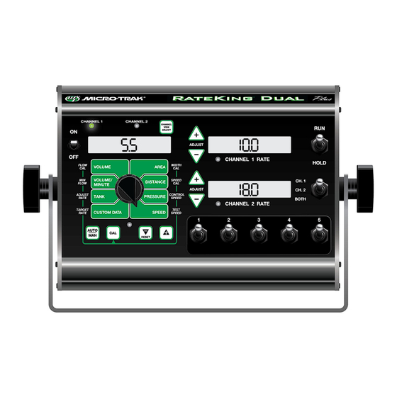
Component Parts and Hardware RateKing Dual Plus Console 3-Section P/N 18717 5-Section P/N 18702 (shown) Reference Manual Console Mount Kit 7-Section P/N 18718 P/N 18836 P/N 13774 5-Section Model 5-Section Branch Harness Ch. 1 Flow Control Harness w/Weather Pack Tower Conn. P/N 18675 P/N 18819 Power Cable... -
Page 6: System Overview
System Overview... -
Page 7: Complete System Wiring Diagram
Complete System Wiring Diagram 5-Section Shown... -
Page 8: Section Branch Harness Wiring Diagram
Branch Wiring Diagrams 3-Section & 7-Section... -
Page 9: Installation
Installation Overview Install the RateKing™ Dual Plus console and system components by following the recommended sequence of steps. Your installation may not include some of these steps; some equipment is optional and some components may already be installed. All installations must follow Calibration and Pre-Field System Checkout steps (9,10) to ensure safe and accurate operation of system. -
Page 10: Console Mounting - Power Connection - Section Wiring
Installation (cont.) Console Mounting - Power Connection - Section Wiring Select a mounting location which is practical and convenient. It should be easy to reach and highly visible to the operator. Mount Knob DO NOT INSTALL IN A POSITION THAT OBSTRUCTS THE Rubber Washer VIEW OF THE ROAD OR WORK AREA. -
Page 11: Speed Sensor Options
Proximity Sensor Micro-Trak® also offers a proximity sensor - P/N 01554 Gear tooth sensor kit. It is useful in situations where it is impractical or inadvisable to use a flowmeter to monitor flow of material. It can also serve as a Speed sensor. The 01554 Gear tooth sensor responds to the close presence of ferrous metals and sends a signal to the console via the Flow or Speed connection. -
Page 12: Optional Equipment - Switches
The connector labelled “SafeGuard Run/Hold” is wired Normally Open. The default polarity for the RateKing Dual Plus Run/Hold circuit is preset to “Closed”, meaning pressure on the switch tip causes the system to “Hold”. See figure 5. The polarity setting can be accessed in Special Calibration settings (see page 23) - it is called “Hold Input Polarity”. -
Page 13: Plumbing Overviews
Installation (cont.) RateKing Dual Plus Plumbing Overview Bypass Configuration - Flow through servo bypasses flowmeter... - Page 14 Installation (cont.) RateKing Dual Plus Plumbing Overview In-Line Configuration - Flow through servo inline with flowmeter...
-
Page 15: System Components
* NOT SUPPLIED Flipping the flowmeter periodically (black nylon and stainless Figure 7 steel Micro-Trak® manufactured models) to reverse the flow will greatly extend the life of the flowmeter. Reversing the flow distributes the bearing wear between the 2 sides. -
Page 16: Bypass Valve
Installation (cont.) System Components Bypass Valve For oversized pumps Bypass Valve With oversized pumps, it may be necessary to install a bypass valve. This valve allows excess flow to return to Tee “C” the tank. This in turn reduces the pump output to the rest of the system. -
Page 17: Feature Summary
Feature Summary Basic Features • Dual Channel Controller - features 2 channels and 4 modes of control - Normal, Parallel, Injection, or Section Assign. • Custom Data - choice of data displayed includes: Target Rate, Output Drive (STD or PWM), VRA info., Elapsed Hours, Area per Hour, Total Width, and Section Status. -
Page 18: Rate Control
(Standard DC drive only). Serial Port • Selectable VRA Serial Protocol (Micro-Trak® or Raven®) to interface with GPS/Mapping Controllers for Variable Rate Application (VRA) including Target Hold. • User can override the GPS/Mapping Controller to apply a rate above or below the prescription rate or override Target Hold. -
Page 19: Channel Operating Modes
Channel Operating Modes Normal Mode: In Normal Mode, Channels 1 and 2 operate independently. Channel 1 has 5 section control switches and Channel 2 has 1 section output (no separate switch). Both channels are controlled by the Run/Hold switch. The working parameters for Width Cal (section width) are independent of each other. Parallel Mode: In Parallel mode, Channels 1 and 2 operate independently but Channel 2 uses section widths defined by Channel 1. -
Page 20: Func Tion Summary
Func tion Summary The RateKing™ Dual Plus features large, easy-to-read liquid crystal displays, easy-to-use rotary dial and lighted panel for night use. The console also includes section switches, an audible alarm, and a serial port. Rotary Dial Positions VOLUME (1) (2) (3): AREA (1) (2) (3): Displays the total Keeps a running... -
Page 21: Calibration
Calibration Before operating the RateKing™ Dual Plus, it is necessary to calibrate it for the intended work and components. IMPORTANT!! The first step is choosing intended UNITS (English, Metric, or Turf) in Special Calibration, page 23. Define UNITS before adjusting any other calibration settings. We recommend to complete all Special Calibration adjustments before returning to Calibration setup. -
Page 22: Calibration Positions
Calibration (cont.) Calibration Positions FLOW WIDTH This po si tion cal i brates the system to the flow- Adjust the effec tive working width, in inch es me ter factory setting. The flowmeter is calibrated (meters) for each section. Enter a value of “0” with water at the factory and assigned a “Liquid (.000) for any unused sec tions. -
Page 23: Special Calibration
Special Calibration Special Calibration mode accesses important system parameters and settings. It is important to remember to select the appropriate channel you wish to adjust - some parameters affect both channels. The UNITS position must be set before changing any other Calibration or Special Calibration settings. These settings enable or disable other setting options to adjust applicable parameters: •... -
Page 24: Special Calibration Steps
MPH (km/H). via serial port, the APPLICATION ID is included with See Appendix E for details. Setting to 0 (Off ) will the Totals Data List and Equipment List information. disable the function. (Micro-Trak® protocol only) - Page 25 (maximum) value for Pressure Sensor. Default setting feature. When transitioning from HOLD to RUN, it is 150 PSI for Micro-Trak Pressure Sensor P/N 18757. provides time for motorized valves to operate and Adjust it to 300 PSI for Micro-Trak P/N 18758.
- Page 26 VRA information through the serial proportional to active width. Example: If the threshold port. Choices are Micro-Trak or Raven (model 660) is set to 10 gpm while running only 2 out of 5 sections, Default is Micro-Trak protocol. (Affects both channels.) the trigger will be on at 4 gpm - (2/5 X 10).
- Page 27 Special Calibration Settings - Page 4 Setting Locations Page Page 1 2 3 4 5 THREE-WAY VALVE ENABLE PWM FREQUENCY FLOW AT MIN. PULSE WIDTH FLOW AT MAX. PULSE WIDTH MINIMUM PULSE WIDTH MAXIMUM PULSE WIDTH AGITATION % or VALVE POLARITY CLOSED / OPEN LOOP THREE-WAY VALVE ENABLE PWM FREQUENCY -...
- Page 28 Special Calibration Settings - Page 5 Setting Locations Page Page 1 2 3 4 5 CUSTOM DATA SELECT RATE ALARM THRESHOLD MULTIFUNCTION B FLOW TRIG. THRESHOLD SECTION INPUT POLARITY MULTIFUNCTION B OUTPUT FIXED MINIMUM FLOW SECTION ASSIGN MODE RATE ALARM THRESHOLD CUSTOM DATA SELECT Location: PAGE 5 - AREA Location: PAGE 5 - VOLUME...
-
Page 29: Operation
Operation Make sure your system is properly calibrated before beginning to apply product. We also recommend completion of the Pre Application System Checkout described on page 32 prior to beginning any operations. Manual Operation This mode sets and maintains a steady flow rate (GPM) not affected by changes in vehicle speed. The overall application rate (GPA) will vary depending on speed (slow vehicle speed = increased application rate, fast speed = lower application rate.) Manual mode is most useful for system set up, spot applications, etc. - Page 30 Operation (cont.) Console Controls (cont.) RATE CHANNEL These buttons are used to temporarily This selects which channel information ADJUST VIEW increase or decrease the application rate, as is displayed in the Data Window. It also BUTTONS SELECT shown in the corresponding channel rate selects channel for Calibration and Special window.
-
Page 31: Additional System Features
If the GMC does chemical spills if the Flow signal is lost. not include ‘Micro-Trak’ as a supported serial If the Flow signal is missing for 15 seconds controller, then the Raven 660 protocol may be or more, it automatically stops the flow used instead (See Special Cal parameter ‘Serial... -
Page 32: Pre-Field Sys Tem Checkout
Pre-Field Sys tem Checkout Before beginning actual operation, perform the following “Pre-Field” procedure for both channels to ensure that your valve settings, nozzle selection and desired speed range will allow the RateKing Dual Plus to provide the required application control. This procedure should be repeated for each new nozzle se lec tion and/or application rate. (Refer to your nozzle selection guide to find the correct nozzle for your speed range.) OPTIMIZING LIQUID FLOW RATE For best performance, adjust the output of the pump so the control valve is operating near mid-position. -
Page 33: Troubleshooting
Troubleshooting Messages/Warnings Indicates a corrupt calibration value. Can only be cleared by entering Calibration or Special Calibration modes, checking and/or changing settings and exiting to save. The message alerts the user that the currently selected counter will be cleared if the reset button is held for 2 seconds. -
Page 34: General
Troubleshooting (cont.) General All Micro-Trak ® products are tested prior to packaging so, BOOM SECTION SHUT-OFF unless there has been damage in shipment, you can be If you are in AUTO with no speed, all the boom sections will confident that everything will be operational when you be automatically shut-off. -
Page 35: Checking Individual Components
12VDC to operate. Also, the Hall- on a Micro-Trak® demonstration dis play. effect sen sor re quires al ter nat ing magnetic po lar i ties in or der HARNESS to switch. -
Page 36: Checking Console Inputs
Troubleshooting (cont.) Checking Console Inputs CONSOLE INPUTS FLOWMETER Shaking the Flowmeter end to end should pro duce a “rattling” If there is no response from any of the following tests, refer to sound (shaft end play). Blowing in the meter from either end the main wiring diagram to locate the next connector in line should spin the turbine freely. -
Page 37: Plumbing Troubleshooting Chart
Plumbing Troubleshooting Chart SYMPTOM POSSIBLE CAUSE POSSIBLE SOLUTION System loses pressure in MANUAL Pump Air-lock • Clean strainer • Install larger hoses Insufficient pressure adjustment in Too much flow restriction in servo loop • Install larger hoses and fittings MANUAL •... -
Page 38: Appendices
Appendices... -
Page 39: Appendix A - Remote Run/Hold Kit Installation
(Black body) “Special” Calibration. Figure 18 Remote Run sensor on hydraulic cylinder. Magnet and sensor are aligned when equipment is lowered and Remote Run/Hold Kit - Micro-Trak® P/N 01535 operating. Includes: • Run/Hold Sensor w/ 3-pin Metri Pack conn. •... -
Page 40: Appendix B - Magnetic Speed Sensor Installation
5. Rounding 5 up to the nearest even number is 6. For this South example, the minimum number of magnets required is 6. The magnets provided by Micro-Trak® are marked with North South a punched dashed line on the SOUTH pole side of the Figure 20 magnet. -
Page 41: Wheel Mounting
Appendix B- Magnetic Speed Sensor Installation (cont.) Wheel Mounting Implement Wheels Speed Sensor and Bracket 1. Secure magnets mechanically or with epoxy. 2. Rigidly mount sensor mounting bracket to the wheel ¼” Bolts, assembly. Cut or bend “L” bracket as required for proper Lockwashers and Nuts positioning of sensor. - Page 42 When distance is set, tight en nuts to lock sensor in detect ed by the Hall-effect speed sen sor must alternate as place. the shaft is turned. The magnets provided by Micro-Trak® • Secure sensor cable to frame with cable ties. Place first are marked with a punched dashed line on the SOUTH pole tie as close to sensor assembly as possible.
-
Page 43: Appendix C - Fine Tuning Speed/Distance Calibration Val Ue
Appendix C - Fine Tuning Speed/Distance Calibration Val ue This procedure is used to verify the Speed/Distance 4. With the rotary dial still at DISTANCE (SPEED CAL), press calibration. In order to achieve accurate measurements, and hold the CAL button for one second. Once the each step in this fine tuning procedure should be con sole is in “CAL,”... -
Page 44: Appendix D - Fine Tuning Flowmeter Calibration Value
Appendix D - Fine Tuning Flowmeter Calibration Value This procedure is used to verify and fine-tune the flowmeter With the console still in the VOLUME position, enter calibration. Every flowmeter is calibrated with water at the calibration, hold the CAL button until the red warning factory and stamped with a calibration val ue. -
Page 45: Appendix E - "Quick Start" Function
Appendix E - “Quick Start” Function There are two different Quick Start methods, “Quick Start - SPEED” and “Quick Start – VALVE”, which can be enabled for use in Automatic operating mode. Each method uses a separate set of Special Calibrate parameters, and only one method can be enabled at a time (the other must be disabled). -
Page 46: Appendix F - "Open Loop" Control & Closed Loop Override
Appendix F - “Open Loop” Control & Closed Loop Override Note: This feature can only be used with a PWM control valve. OVERVIEW Ideally an automatic control system is run using Closed Loop operation which uses feedback from a flow meter (or motor RPM sensor) to adjust the application rate based on ground speed. -
Page 47: Appendix G - Pulse Width Modulation (Pwm) Live Calibrate
Appendix G - Pulse Width Modulation (PWM) Live Calibrate LIVE CALIBRATE is only used in PWM Drive. See “SPECIAL” In Closed Loop, LIVE CALIBRATE allows the user to adjust CALIBRATE for information on setting the output to PWM the Min or Max PW factor and then immediately see how and selecting Open or Closed Loop operation. -
Page 48: Closed Loop Operation
Appendix G - Pulse Width Modulation (PWM) Live Calibrate Closed Loop Operation When satisfied with the minimum flow rate and In Closed Loop operation, a flowmeter is available to measure the flow so all four calibrate factors can be programmed minimum PWM then press the CAL button to toggle interactively using the following procedure. -
Page 49: Open Loop Operation
Appendix G - Pulse Width Modulation (PWM) Live Calibrate Open Loop Operation In Open Loop operation, a flowmeter is not available to 11. Select the FLOW @ MIN PW (Volume/Minute) position. measure the flow so a calibrated container must be used to This will enable a 30 second Timer when the pump is measure the actual flow using the following procedure. - Page 50 Appendix G - Pulse Width Modulation (PWM) Live Calibrate Open Loop Operation 18. When satisfied that MAX PW has been set correctly, press the CAL button to toggle the pump off. If desired, the MAX PW can be written down for future reference. 19.
-
Page 51: Appendix H - Pressure Based Control
Appendix H - Pressure Based Control Enabling RateKing Dual Plus can be configured for Pressure Based Control by entering Calibration and adjusting the Flow Cal number to 0. In addition, MIN FLOW and MIN PRESSURE parameters must also be set or the system will not operate. The MIN PRESSURE parameter is only visible and accessible when Pressure Based Control has been enabled;... -
Page 52: Appendix I - Nh3 Control
Appendix I - NH3 Control System Layout... - Page 53 Appendix I - NH3 Control Wiring Connections for NH3 Channel 1 - Single Section Flowmeter Servo To Console Shut-off Valve (multifunction - Master) Note: for Multi-section application of NH3 on Channel 1, connect the sections to the P/N 18819 Branch Harness. See page 7 for wiring details. Channel 2 - Single Section (only) Flowmeter To Console...
- Page 54 Appendix I - NH3 Control Typical Installation for NH3 GPS Speed Sensor RateKing™ Dual Plus (Other options available) Console Battery Main Harness Hitch Connection Liqui er™ Series Heat Exchanger Nurse Tank...
-
Page 55: Extension Cables
Appendix I - NH3 Control Connection to Liquifier™ NH3 Kits hannel An NH3 system can be connected to Channel 1 using Channel 1 Flow Control Harness (P/N 18675) shown here. Choose an appropriate length extension cable (for example, P/N 13221 shown below). See Appendix M for various extension lengths. - Page 56 Appendix I - NH3 Control Liquifier Installation LIQUIFIER KIT INSTALLATION Remove any existing metering valves. If the old metering valve has a built-in manifold, it is recommended to install a separate new manifold for the Liquifier™ kit. Another option, although not recommended, is to use the existing manifold, making certain the old metering valve is in the maximum open position to allow for minimal restriction of flow through the plumbing.
-
Page 57: Electrical Connections
Appendix I - NH3 Control Liquifier™ Series - Vapor Line Installation FOR ALL NH3 KITS Locate the 1/2” EVA vapor hose supplied with the kit. Starting on one half of the tool bar, connect the 1/2” hose Weld the steel vapor tubes to the back of your liquid to the outside steel vapor tube. - Page 58 Appendix I - NH3 Control Console Setup & Calibration for NH3 Application To begin setup the RateKing™ Dual Plus console for NH3 application, first enter Special Calibration mode: 1. Turn the console OFF. 2. For safety, place system in HOLD via the RUN/HOLD switch. 3.
- Page 59 This po si tion is used to cal i brate the system to the flow me ter for ac cu rate NH3 mea sure ment. The flowmeter has been calibrated at the factory. Enter the “Micro-Trak NH3 cal” number found on the plastic tag attached to the flowmeter.
- Page 60 Appendix I - NH3 Control Console Setup & Calibration for NH3 Application WIDTH Use the Increase/Decrease switches to adjust the number to the working width of your tool bar in inches (thousandths of meters). The “working” width is the width of ground being affected by any operation - for NH3, this equals the number of knives times the spacing.
- Page 61 Appendix I - NH3 Control Fine Tuning Flow Calibration Val ue - NH3 Systems This procedure is used to verify and fine-tune the flowmeter calibration. Every flowmeter is calibrated with water at the factory and stamped with a calibration val ue. Enter that value as a starting point and use this pro ce dure to fine-tune that value for your specific in stal la tion and NH3 application (Please refer to Flow Cal page 59).
- Page 62 Appendix I - NH3 Control Field Operation - Troubleshooting for NH3 Always follow accepted safety precautions. Make sure that equipment is in good operating order. Before connecting the nurse tank to the applicator, check the electric shut-off valve of the RateKing™ Dual Plus system for proper operation. After changing nurse tanks or after other periods of long shut-down, operate the system in MANUAL until the application rate stabilizes.
- Page 63 Appendix I - NH3 Control Flowmeter Assembly (FM-750 N) IMPORTANT: TO ASSEMBLE THE FLOWMETER Opening the flowmeter will void the Flow Calibration value assigned to your unit. However, you may Place the servo, flowmeter end up, in a vice or other suitable need to take the flowmeter apart for periodic cleaning or to fixture.
- Page 64 Appendix I - NH3 Control Flowmeter Assembly (FM-1500 N) IMPORTANT: Opening the flowmeter will void the Flow Calibration value assigned to your unit. However, you may need to take the flowmeter apart for periodic cleaning or to remove an obstruction. See Illustration below for flowmeter reassembly instructions.
-
Page 65: Appendix J - Default Calibration Values
Flush Delay Time Flush Time Audible Alarm Enable Minimum Speed Alarm 0 MPH 0 kph 0 MPH Serial VRA Protocol Micro-Trak Micro-Trak Micro-Trak Manual Control Enable PWM Frequency (PWM) 200 Hz 200 Hz 200 Hz Flow @ MAX PW (PWM) -
Page 66: Appendix K - Radar Adapter Cables
Appendix K - Radar Adapter Cables In-Cab Case MX Series Britax Connector Vansco Radar Amp Connector P/N 18319 P/N 14926 Signal Ground DICKEY-john Radar Amp Connector P/N 14812 In-Cab John Deere Metri-Pack Connector P/N 14810 8000/9000 Series 1. Ground 1. Ground 2. -
Page 67: Appendix L - Conversion Chart
Appendix L - Conversion Chart English to Metric Metric to English When You Know Multiply By To Find When You Know Multiply By To Find LINEAR MEASUREMENT LINEAR MEASUREMENT inches 25.4 millimeters millimeters .039 inches feet 0.305 meters meters 3.28 feet yards 0.914... -
Page 68: Appendix M - Replacement Parts List
Appendix M - Replacement Parts List The following replacement parts are available from your dealer or distributor. A Dealer Locator can be found online at http://www.micro-trak.com/where-to-buy/dealer-locator. DESCRIPTION 01410 Astro II GPS Speed Sensor 01425 Astro 5 GPS Speed Sensor 01531... - Page 69 NOTES...
- Page 70 1305 Stadium Road, Mankato, MN 56001-5355 Toll-Free: 800-328-9613 507-257-3600 www.micro-trak.com • email: trakmail@micro-trak.com Copyright © 2021 Micro-Trak® Systems, Inc. • P/N 18836 A 061522...
Need help?
Do you have a question about the RateKing Dual Plus and is the answer not in the manual?
Questions and answers