Table of Contents
Advertisement
Quick Links
Accessory
Haz Loc Wireless
Remote & Meter /
Solenoid Barriers
Components that allow the installation of a ProDispense™ user-interface and fluid control
in a hazardous location. For professional use only.
26C266
Hazardous Location Wireless Remote
25E765
Meter Barrier Enclosure Assembly
25B223
Solenoid and Meter Barrier Enclosure Assembly, with
Solenoid
Important Safety Instructions
Read all warnings and instructions in this
manual and in your dispensing
operations manual before using the
equipment. Save these instructions.
Hazardous Location Wireless Remote
Barrier Enclosure Assembly
3A6715B
EN
Advertisement
Table of Contents

Related Manuals for Graco 26C266


Summary of Contents for Graco 26C266
- Page 1 Remote & Meter / Solenoid Barriers 3A6715B Components that allow the installation of a ProDispense™ user-interface and fluid control in a hazardous location. For professional use only. 26C266 Hazardous Location Wireless Remote Hazardous Location Wireless Remote Barrier Enclosure Assembly 25E765...
-
Page 2: Table Of Contents
Node ....... . . 28 26C266 Wireless Remote ....9 Remote Control and Indicator Enclosure . -
Page 3: Overview
Banner Engineering’s FlexPower® power management technology to operate wireless nodes (1), remotes The barrier enclosure assemblies (25E765 and 25B223) (sensors) (3), and gateways (4). See 26C266 Kit use R. STAHL’s safety barrier technology for field Component Identification on page 15. -
Page 4: Barrier Enclosure
Barrier Enclosure Barrier Enclosure Barrier Enclosure Assemblies Assembly Component Description 111985 - Provides power and signal interface to the Graco G3000 meter sensor. Dual-channel Stahl Barrier 25E765 - 17C888 - Pre-wired to the barrier, using individually-shielded twisted-pair cables Meter Barrier 50 ft Meter Cable selected to be used in hazardous locations. -
Page 5: Barrier Enclosure Component Entity Parameter Data
T3, and Class I Zone 0; 2 I G Ex (ia Ga) IIB/IIC T4 Gc. Sensors (G3000 Sensors only; p/n 24W650 or 24W651) are approved through Graco. Class I, Div 1, Group D T3, UL 698A and Class I, Zone 0;... -
Page 6: Barrier Enclosure Installation
Barrier Enclosure Barrier Enclosure Installation Grounding WARNING WARNING FIRE AND EXPLOSION HAZARD Do not substitute or modify system components as This equipment must be grounded to reduce the risk this may impair intrinsic safety. Do not install of static sparking and electric shock. Electric or static equipment approved only for a non-hazardous sparking can cause fumes to ignite or explode. -
Page 7: Typical Barrier Enclosure Installation
12 ProDispense Fluid Panel 13 Dispense Valve* Barrier Enclosure Wiring Diagram Non-Hazardous Location Hazardous Location PRODISPENSE FLUID PANEL 26A131 / 26A132 / 26A165 ENCLOSURE METER CABLE CONNECTS TO 111985 GRACO METER 50 FT. WHITE BARRIER WHITE WHITE METER CABLE SENSOR 24W650/24W651 BLACK BLACK BLACK GND. -
Page 8: Barrier Enclosure Control Drawing
Ex 2 I G Ex ia IIB T3 Class I, Div 1, Group C,D T3 Meter cable, 50 ft Meter sensor, p/n 19A751 Barrier dual channel p/n 111985 Graco 24W650 / Stahl 9002/13-280-110-001 24W651. Entity Parameters Entity Parameters Uo 28 Volts... -
Page 9: 26C266 Wireless Remote
26C266 Wireless Remote 26C266 Wireless Remote Components The 26C266 wireless remote allows for limited operation of a ProDispense from a user-interface located in a hazardous location. The kit is comprised of three major components and a conductor cable. NOTE: The ProDispense must have software revision 1.03.007, or higher, to be functional with the 26C266 Wireless Remote kit. -
Page 10: 26C266 Wireless Remote Approvals
26C266 Wireless Remote 26C266 Wireless Remote Approvals Part No. Description Approvals through Banner Engineering 17V930 Transceiver node only. Battery-operated, with entity parameter-approved input/output interface, with 1725 indicator lights and switches. See 26C266 Wireless Control Approvals CSA - C/US Drawing, on page 14, for entity Class I, Division 1, Groups A, B, C, D;... -
Page 11: Wireless Remote Kit Installation
Gateway Modules (4): Mount to a grounded structure ProDispense Control Panel (11) and Fluid Panel (12). to prevent static build-up. See F . 4. See 26C266 Kit Mounting Instructions, page 16, and Cable Connections, page 17, for more detailed ProDispense Components (9-13): Ground as instructions. -
Page 12: Typical Installation
26C266 Wireless Remote Typical Installation This is an example of how a standalone wireless remote kit could be integrated into a ProDispense setup. The notes include information for including barrier assembly kits this integration. Non-Hazardous Location Hazardous Location † †... -
Page 13: 26C266 Wireless Electrical Schematics
CONNECTS TO FCM M8 INPUT CONNECTION AT THE FOR FLUID PLATE 1 OR 2 BLUE BLUE BLUE 17V933 GATEWAY BLACK BLACK BLACK BROWN WHITE CONNECTS TO FLUID PLATE J BOX M8 CONNECTOR BLUE BLACK . 5 26C266 Wireless Electrical Schematics 3A6715B... -
Page 14: 26C266 Wireless Control Drawing
Pi 3400 mW Ci 0.56 µF 140 µH See the manufacturer’s control drawing for the wireless transmitter and indicator lights. Install in accordance with the National Electrical Code (NEC) and any applicable local codes. . 6 26C266 Wireless Control Drawing 3A6715B... -
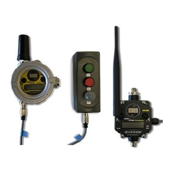
Page 15: 26C266 Kit Component Identification
26C266 Kit Component Identification Non-Hazardous Location Hazardous Location Start Stop Indicator Light . 7 26C266 Kit Components Key: Node, wireless transmitter Conductor Cable; 10 ft. Remote Operator Station with LED Indicator Gateway (locate so cable can reach FCM, Port ) Cable, signal... -
Page 16: Gateway Component Identification
26C266 Wireless Remote Gateway Component Identification 26C266 Kit Mounting Instructions Inside Hazardous Location The node (1) and remote operator (3) station are located inside the hazardous location. See F . 4. • Use the holes in the housings as templates for the mounting hole patterns. -
Page 17: Cable Connections
26C266 Wireless Remote Cable Connections 1. Use the conductor cable (2) provided to connect the Port 3 remote operator station (3) to the node (1), as shown in F . 7. NOTE: The node (1) has a D-cell battery pre-installed. No power connection is needed. (See Battery Replacement on page 24 to replace the battery.) -
Page 18: Set Up Wireless Network
Set Up Wireless Network NOTE: The 26C266 Hazardous Location Wireless 4. Connect power to all devices. Once powered, the Remote kit is shipped from Graco with necessary gateway’s LED 1 should be a solid green and the configurations and bindings already completed. These node’s LED 2 should be flashing red, indicating... -
Page 19: Operation
26C266 Wireless Remote Operation Test the Remote Operator Station and Node Remote Operator Station Functions and Indicators 1. Power on the ProDispense System. Start Button 2. Observe the indicator light on the remote operator station (3): • Starts a recipe dispense. -
Page 20: Troubleshooting
Common Troubleshooting Issues For more detail, refer to the Banner Engineering manual shipped with your 26C266 Wireless Remote Kit. Problem Cause Solution The radio won’t wake up. -
Page 21: Led Message Codes
Flashing amber Gateway, Remote I/O: Active Modbus communication Flashing red Flashing red Device error. If the LCD also reports BAD EE, contact your Graco representative for replacement. Flashing red Gateway, Remote I/O: Modbus communication error For a GatewayPro system, a Modbus communications error indicates a communications problem internal to the GatewayPro. - Page 22 Troubleshooting LED 1 LED 2 Definition/Solution Flashing red Node: No radio communication There are two settings on every node device used to synchronize to the gateway device: • The node must be bound to the gateway. • Each node ID with that network must be set to a unique number. Solutions: 1.
-
Page 23: Lcd Message Codes
Troubleshooting LCD Message Codes Message Solution BAD EE System Error. A system error typically represents a failure of the EE PROM. Contact the factory for replacement. EC XX The XX refers to the Modbus register 8 message code shown in Modbus Message Codes for Register 8. -
Page 24: Repair
3. Remove the existing battery from the battery holder. comply with all local codes and regulations. 4. Insert the new battery (only use Graco part 19A792) After any service or repair, refer to Grounding on into the battery holder, verifying the positive and... -
Page 25: Parts
Parts Parts Barrier Enclosure Assembly 25B223 shown, with second barrier for solenoid valve Barrier Enclosure Parts List Ref. Part Description Ref. Part Description 514895 Barrier, solenoid Enclosure 111987 Strain relief, cable 111985 Barrier, meter 19A947 Cable; 36 in. 194751 Connector, meter 19A948 Cable;... -
Page 26: 26C266 Hazardous Location Wireless Remote
Parts 26C266 Hazardous Location Wireless Remote Hazardous Location Non-Hazardous Location 26C266 Hazardous Location Wireless Remote Parts List Ref. Part Description 17V930 Node 17V931 Cable, 8 conductor, 3m, m12, m to f 17V932 Remote control and indicator enclosure 17V933 Gateway 17V934 Cable, signal, 8p, 3m, m12, m/fl 17V935 Cable, adapter, 0.5m, m12f/m8f... -
Page 27: Dimensions
Dimensions Dimensions Barrier Enclosure 3A6715B... -
Page 28: Gateway
Dimensions Gateway Units Millimeters [Inches] Node 3A6715B... -
Page 29: Remote Control And Indicator Enclosure
Dimensions Remote Control and Indicator Enclosure 3A6715B... -
Page 30: Appendix A - Factory Settings
Graco personnel. The User Configuration Tool (UCT) allows users to link I/O points in the wireless network, view I/O register The 26C266 Hazardous Location Wireless Remote has values, and set system communication parameters been pre-configured for proper functionality between the when a host system is not part of the wireless network. -
Page 31: Appendix B - Conducting A Site Survey
Appendix B - Conducting a Site Survey Appendix B - Conducting a Site Survey A site survey, or Radio Signal Strength Indication 8. To end the site survey, double-click button 2. (RSSI), analyzes the radio communication link between 9. Change the gateway’s right rotary dial back to 0. the gateway and any node within the network by The LCD displays the device readings for the analyzing the radio signal strength of received data... -
Page 32: Improving Site Survey Results
Appendix B - Conducting a Site Survey Improving Site Survey Results Good or weak signal strength equals some yellow If your site survey results have more yellow than green, consider replacing the node’s antenna with one of the signals and a majority of red signals (very few green following: signals, a small number of yellow signals, and a small to medium number of missed signals) or one to two flashes... -
Page 33: Technical Specifications
Multiple metal obstructions 10 - 100 ft (3.0 - 30.5 m) FCC / IC Notice 26C266 Assembly (17V930 and 17V933 models) FCC Certification, 900 MHz Complies with Part 15 of the FCC rules and regulations. FCC ID: TGUDX80 This device complies with Part 15 of the FCC Rules. Operation is subject to the following two conditions: (1) this device may not cause harmful interference, and (2) this device must accept any interference received, including interference that may cause undesired operation. -
Page 34: Graco Standard Warranty
With the exception of any special, extended, or limited warranty published by Graco, Graco will, for a period of twelve months from the date of sale, repair or replace any part of the equipment determined by Graco to be defective.
Need help?
Do you have a question about the 26C266 and is the answer not in the manual?
Questions and answers