Graco G3000 Instructions-Parts List Manual
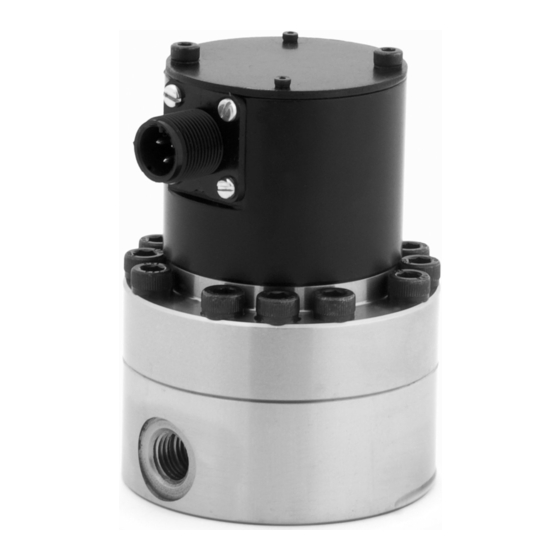
Volumetric fluid flow meter.
for precise metering of plural component fluids or solvents (depending on model).
for professional use only.
Hide thumbs
Also See for G3000:
- Instructions manual (42 pages) ,
- Instructions-parts list manual (18 pages) ,
- Instructions and parts (18 pages)
Table of Contents
Advertisement
Instructions-Parts
Volumetric Fluid Flow
Meter
For precise metering of plural component fluids or solvents (depending on model).
For professional use only.
See page 3 for model information, including maximum working pressure.
Important Safety Instructions
Read all warnings and instructions in this
manual. Save these instructions.
G3000, G3000A, and G3000HR
3151640
Class I, Div 1, Group D,
T3 (Ta = 0° - 60°C)
II 1 G
Ex ia IIA T3
0°C<Ta<60°C Ga
ITS12ATEX27565X
0359
Intrinsically Safe for Hazardous Locations (Class I; Division
1; Group D) when used with an approved barrier only.
S3000 Solvent Meter
TI11579a
G250 and G250HR
308778Y
EN
TI14674b
TI13038a
Advertisement
Table of Contents

Subscribe to Our Youtube Channel
Related Manuals for Graco G3000


Summary of Contents for Graco G3000
- Page 1 See page 3 for model information, including maximum working pressure. Important Safety Instructions Read all warnings and instructions in this manual. Save these instructions. S3000 Solvent Meter G3000, G3000A, and G3000HR 3151640 Class I, Div 1, Group D, T3 (Ta = 0° - 60°C) TI11579a...
-
Page 2: Table Of Contents
Operation ....... . 10 Graco Information ......24 Pressure Relief Procedure . -
Page 3: Meter Models
For use with ProMix 2KS Wall Fluid Panel. Kits include meter, cable, fluid tube, check valve, mounting bracket and hardware. Kit Part No. Meter 15V804 Part No. 289813 G3000 Meter 15V827 Part No. 289814 G3000HR Meter 826216 Part No. 26A119 G3000A Meter Solvent Meter Kit For use with ProMix 2KS Wall Fluid Panel. -
Page 4: Warnings
Warnings Warnings The following warnings are for the setup, use, grounding, maintenance, and repair of this equipment. The exclama- tion point symbol alerts you to a general warning and the hazard symbols refer to procedure-specific risks. When these symbols appear in the body of this manual, refer back to these Warnings. Product-specific hazard symbols and warnings not covered in this section may appear throughout the body of this manual where applicable. - Page 5 Warnings SPECIAL CONDITIONS FOR SAFE USE Equipment must comply with the following conditions to avoid a hazardous condition which can cause fire, explosion, or electric shock: • Sensor housing is of aluminum construction. Precautions must be taken to avoid impacts or contact with moving parts.
- Page 6 Warnings EQUIPMENT MISUSE HAZARD Misuse can cause death or serious injury. • Do not operate the unit when fatigued or under the influence of drugs or alcohol. • Do not exceed the maximum working pressure or temperature rating of the lowest rated system component.
-
Page 7: Installation
Installation Installation Installing the Flow Meter NOTE: You must assemble the meter sensor to the meter body before connecting the cable to the sensor for the meter to function properly. Improper wiring can cause fire and explosion, electric shock, or other serious injury. •... -
Page 8: Intrinsically Safe Installation Requirements
Ii/Imax = 110 mA Barrier System Ci = 0.4 microFarads Cable Shield Li = 0.01 mH Pi = 0.8 W Flow Meter Body G3000 G3000HR 250 VAC Maximum G250 Ground Supply Voltage G250HR S3000 NOTE: See Intrinsically Safe Installation Requirements above. -
Page 9: Grounding
Installation Grounding a. Mount the meter to a grounded conductive sur- face, or b. Connect the conductive fluid hose to the meter inlet and outlet, or The equipment must be grounded to reduce the risk of static sparking and electric shock. Electric or c. -
Page 10: Operation
(cc) and read the volume on the which produces an impulse for every gear tooth passing flow meter monitor. G3000, G3000A, and G250: If the flow meter scale factor is not between 0.112-0.140 cc/pulse, follow Recommended Usage the cleaning procedure on page 13, then recalibrate the flow meter. -
Page 11: Troubleshooting
Troubleshooting Troubleshooting Before servicing this equipment always make sure to relieve the pressure. NOTE: The sensor is not a serviceable part. Replace it if it is malfunctioning. Problem Cause Solution No flow volume displayed at monitor- Flow volume is too low to measure. Increase flow volume. -
Page 12: Maintenance
Maintenance Maintenance Flushing Improper wiring can cause fire and explosion, electric shock, or other serious injury. • Disconnect power source before installing. Flush the fluid supply line and meter fluid reservoir daily with a compatible solvent as instructed below. • All electrical equipment must only be installed by a qualified electrician. -
Page 13: Cleaning Or Servicing The Meter Chamber
11. Install the screws. Tighten them oppositely and Use only genuine Graco replacement parts. Substitu- evenly. Tighten to 12 ft-lb (16 N•m) for 289813, tion of components may impair intrinsic safety. This 289814, and 26A119. -
Page 14: Cleaning Or Servicing The Solvent Meter
Do not install or service this equipment unless you are trained and qualified. Use only genuine Graco replacement parts. Substitu- TI16684a TI16685a tion of components may impair intrinsic safety. This could result in a failure which causes serious injury . -
Page 15: Parts
280555; see page 18 Ref. Part No. Description 114339 UNION, swivel; 1/4 npt(m) x 1/4 npsm(f) 289813 METER, gear, G3000; used on 166846 ADAPTER; 1/4 npt x 1/4 npsm 15V804; see page 16 26A119 METER, gear, G3000A; used on (mbe) 826212;... -
Page 16: Bare Meter Assemblies
Parts Bare Meter Assemblies 289813 G3000 Meter 26A119 G3000A Meter 289814 G3000HR Meter Ref. Part No. Description 114100 SCREW, socket-hd; M4 x 55 mm long 24W651 ELECTRONIC SENSOR** 239719 GEAR METER ASSEMBLY; includes items 4-11; used on 289813 26A118 GEAR METER ASSEMBLY;... - Page 17 Parts 249426 G250 Meter 249427 G250HR Meter Ref. Part No. Description 111308 SCREW, cap, socket-hd HOUSING, upper 110588 O-RING; ptfe 239718 GEAR; used on 249426 244290 GEAR; used on 249427 192383 SHAFT, gear; used on 249426 197142 SHAFT, gear; used on 249427 192387 PIN, locating HOUSING, lower 15F866 SPACER...
-
Page 18: Solvent Meter Assembly
Parts Solvent Meter Assembly 258718 S3000 Meter Ref. Torque to 27-57 Part No. Description in-lb (3.1-6.4 N•m). 114100 SCREW, socket-hd; M4 x 55 mm Torque to 11 ft-lb long (15 N•m). 24W650 ELECTRONIC SENSOR** 24G951 GEAR METER ASSEMBLY; used on 258718; includes items 3a-3f •... - Page 19 Parts 308778Y...
-
Page 20: Dimensions
Dimensions Dimensions G3000, G3000A, and G3000HR G250 and G250HR Mounting Holes (bottom Mounting Holes (bottom 1.73 in. (43.94 mm) 1.73 in. TI13043a (43.94 mm) TI7382a Part Nos. 249426 and 249427 Part Nos. 289813, 289814, and 26A119 3.75 in. (95.25 mm) 1/4-18 npt(f) 4.00 in. - Page 21 Dimensions Solvent Meter Part No. 258718 Mounting Holes (bottom 3.71 in. 1/4-18 npt(f) 2.36 in. (94.2 mm) inlet/outlet (60 mm) 1.96 in. (49.8 mm) 1.75 in. (44.45 mm) 3.15 in. TI14680a (80 mm) TI14674b Kit Mounting Bracket Part No. 15U749 0.44 in.
-
Page 22: Technical Data
Technical Data Technical Data Volumetric Fluid Flow Meters U.S. Metric Maximum Fluid Working Pressure G3000, G3000A, and G3000HR 4000 psi 28 MPa, 276 bar S3000 Solvent Meter 3000 psi 21 MPa, 210 bar G250 and G250HR 300 psi 2.1 MPa, 21 bar... -
Page 23: Pressure Drop Curve
Pressure Drop Curve Pressure Drop Curve 500 cps 400 cps 300 cps 200 cps 100 cps 50 cps G3000/G3000A gal/min G250 0.40 G3000HR/G250HR 0.05 0.10 0.15 0.20 0.25 0.30 0.35 0.45 0.50 0.55 gal/min 0.16 S3000 0.025 0.05 0.065 0.076 0.083 0.10 0.13... -
Page 24: Graco Standard Warranty
With the exception of any special, extended, or limited warranty published by Graco, Graco will, for a period of twelve months from the date of sale, repair or replace any part of the equipment determined by Graco to be defective.
Need help?
Do you have a question about the G3000 and is the answer not in the manual?
Questions and answers