Table of Contents
Advertisement
Quick Links
Repair/Parts
ProMix
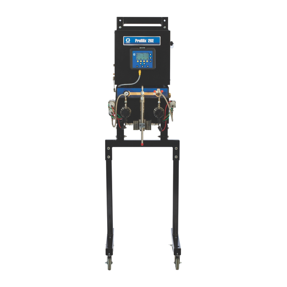
Plural Component Proportioner
Self-contained, electronic plural component paint proportioner. For professional use only.
Important Safety Instructions
Read all warnings and instructions in this
manual. Save these instructions.
See pages 4 and 5 for model information, including maximum working pressure and approvals.
For patent information, see www.graco.com/patents
Pump System
®
2KE
ti15696a
Meter System
3A0870S
EN
ti15698a
Advertisement
Table of Contents

Related Manuals for Graco ProMix 2KE


Summary of Contents for Graco ProMix 2KE
- Page 1 Self-contained, electronic plural component paint proportioner. For professional use only. Important Safety Instructions Read all warnings and instructions in this manual. Save these instructions. See pages 4 and 5 for model information, including maximum working pressure and approvals. For patent information, see www.graco.com/patents Pump System Meter System ti15696a ti15698a...
-
Page 2: Table Of Contents
Pump System Air Controls ....25 Graco Standard Warranty ....72 Meter System Air Controls . -
Page 3: Related Manuals
Related Manuals Related Manuals Manual Description 3A0868 ProMix 2KE, Pump-Based, Operation 3A0869 ProMix 2KE, Meter-Based, Operation 313599 Coriolis Meter 308778 G3000 Flow Meter 312781 Fluid Mix Manifold 312782 Dosing Valve 312784 Gun Flush Box Kit 15V826 312792 Merkur Displacement Pump... -
Page 4: Non-Hazardous Location Models
3000 (20.68, 206.8) 3 color/1 catalyst ProMix 2KE non-hazardous location equipment manufactured in the United States, with serial number beginning with A or 01, has FM and CE approvals. Equipment manufactured in Belgium, with serial number beginning with M or 38, has CE approval. -
Page 5: Hazardous Location Models
Hazardous Location Models Hazardous Location Models ProMix 2KE systems are not approved for use in hazardous locations unless the base model, all accessories, all kits, and all wiring meet local, state, and national codes. Approved for Hazardous Location Class 1, Div 1, Group D (North America); Class 1, Zones 1 and 2 (Europe) -
Page 6: Warnings
Warnings Warnings The following warnings are for the setup, use, grounding, maintenance, and repair of this equipment. The exclama- tion point symbol alerts you to a general warning and the hazard symbols refer to procedure-specific risks. When these symbols appear in the body of this manual, refer back to these Warnings. Product-specific hazard symbols and warnings not covered in this section may appear throughout the body of this manual where applicable. - Page 7 Warnings WARNING INTRINSIC SAFETY Intrinsically safe equipment that is installed improperly or connected to non-intrinsically safe equipment will create a hazardous condition and can cause fire, explosion, or electric shock. Follow local regulations and the following safety requirements. • Only models with model numbers 24Z013, 24Z014, 24F084-24F087, 24F102-24F115, and 24Z018, utilizing the air-driven alternator, are approved for installation in a Hazardous (explosive atmosphere) Location.
- Page 8 Warnings WARNING EQUIPMENT MISUSE HAZARD Misuse can cause death or serious injury. • Do not operate the unit when fatigued or under the influence of drugs or alcohol. • Do not exceed the maximum working pressure or temperature rating of the lowest rated system component.
-
Page 9: Important Two-Component Material Information
Important Two-Component Material Information Important Two-Component Material Information Material Self-ignition Isocyanates (ISO) are catalysts used in two component materials. Isocyanate Conditions Some materials may become self-igniting if applied too thick. Read material manufacturer’s warnings and Safety Data Sheet (SDS). Spraying or dispensing materials that contain isocyanates creates potentially harmful mists, Keep Components A and B vapors, and atomized particulates. -
Page 10: Moisture Sensitivity Of Isocyanates
Important Two-Component Material Information Moisture Sensitivity of NOTE: The amount of film formation and rate of crystal- lization varies depending on the blend of ISO, the Isocyanates humidity, and the temperature. Exposure to moisture (such as humidity) will cause ISO Changing Materials to partially cure;... -
Page 11: Important Acid Catalyst Information
Important Acid Catalyst Information Important Acid Catalyst Information The 2KE Plural Component Proportioner is designed for acid catalysts (“acid”) currently used in two-component, wood-finishing materials. Current acids in use (with pH levels as low as 1) are more corrosive than earlier acids. More corrosion-resistant wetted materials of construction are required, and must be used without substitution, to withstand the increased corrosive properties of these acids. -
Page 12: Pressure Relief Procedure
B fluid supply pumps/pressure pots. NOTE: The following procedure relieves all fluid and air 3. Remove the Control Box cover. pressure in the ProMix 2KE system. 4. With the gun triggered, push the manual override on Pump Systems the A1 (A2, A3), and B dose valve solenoids to relieve pressure. -
Page 13: Purging
Purging Purging Pump Systems If the gun flush box is not used, trig- ger the gun into a grounded metal pail until the purge sequence is com- There are 2 pump purging procedures in this manual: plete. • Purging Mixed Material •... -
Page 14: Meter Systems
Purging 5. Disconnect the component A and B fluid supplies at the pump inlets, and connect solvent supply lines. 1. Press on Run Mix Spray (Screen 2) or from any screen to put the system in Standby. 6. Adjust the solvent fluid supply pressure. Use the lowest possible pressure to avoid splashing. - Page 15 2. Close main air shutoff valve on air supply line and mendations. Maintenance needs will vary based on indi- on ProMix 2KE. vidual applications and material differences. 3. Non-IS Systems: Shut off ProMix 2KE power (0 position). NOTE: Meter-based systems will Recommended Maintenance restart in Recipe 0.
-
Page 16: Service
Service Service Before Servicing 4. Remove and replace element (206a, 209a). 5. Screw filter bowl (B) on securely. Install cover (A). Pump • To avoid electric shock, turn off power before System servicing. • Servicing the Control Box exposes you to high voltage. -
Page 17: Replace Solenoids
Service Replace Solenoids The system has a minimum of 4 solenoids. If you have a To replace the solenoid module: 3-color system or a gun flush box, you have additional (optional) solenoids for each. 1. Follow Before Servicing, page 16. Disconnect main power. -
Page 18: Replace The Power Supply
Service Replace the Power Supply 10. Connect the power supply wire harness (411/PS) to the switch (402), as shown. See also Electrical Schematic. Connect the PS ground wire to the ground terminal (T) of the advanced fluid control module. All electrical wiring must be completed by a qualified 11. - Page 19 Service 5: PS(L) 2: PS(N) 4: LF(L) 1: LF(N) 401a LF(L) LF(N) PS(L) PS(N) PS(GND) ti16454c . 8. Replace Wall Power Supply 3A0870S...
- Page 20 Service Alternator Power Supply and Turbine 5. Disconnect air regulator line and exhaust air line from alternator module. 1. Follow Before Servicing, page 16. Disconnect main air. 6. Remove four screws (509) from mounting to remove alternator from control box. 2.
-
Page 21: Replace Alternator Regulator
Service Replace Alternator Regulator Replace Advanced Fluid Control Module (AFCM) 1. Follow Before Servicing, page 16. Disconnect main air. 2. Open Control Box. 3. Disconnect supply air line from regulator assembly 1. Follow Before Servicing, page 16. Disconnect (505). main power. 4. -
Page 22: Replace Alarm
Service Replace Alarm Replace Display Module 1. Follow Before Servicing, page 16. 2. The Display Module (63) snaps tightly into the mounting bracket (49). To remove it, lift up on the 1. Follow Before Servicing, page 16. Disconnect front of the bracket and, at the same time, pull the main power. -
Page 23: Replace Usb Module
Service Replace USB Module USB Module 1. Follow Before Servicing, page 16. Disconnect main power. 2. Open Control Box. Advanced 3. Non-IS Systems: Disconnect Display Module CAN Fluid Control cable, Advanced Fluid Control Module CAN cable Module ti16580a and USB cable from the USB module (340). IS Systems: Disconnect Alternator CAN cable and Display Module USB cable from the USB module (340). - Page 24 Service 341 (X 4) ti16451a . 16. Replace USB Module 3A0870S...
-
Page 25: Pump System Air Controls
Service Pump System Air Controls Replace Pressure Gauge(s) 1. See Remove Air Control Assembly, page 25. See F . 18, page 26, for a full diagram of the pump air Remove Air Control Assembly controls. 1. Follow Before Servicing, page 16. 2. -
Page 26: Meter System Air Controls
Service 202b 202a ti16325a . 18. Air Controls, Pump System Meter System Air Controls Solenoid Remove Air/Fluid Panel 1. Follow Before Servicing, page 16. 2. Disconnect main air line and solenoid air line. Dis- connect fluid lines where they enter the valve stacks. - Page 27 Service Replace Ball Valve Replace Pressure Gauge(s) 1. See Remove Air/Fluid Panel, page 26. 1. See Remove Air/Fluid Panel, page 26. 2. Remove screw (106b) and washer (106c) from the 2. Disconnect air line to gauge (105). handle on the front of the panel. 3.
-
Page 28: Fluid Controls
Service Fluid Controls Remove Dosing Valve Stacks 1. Follow Before Servicing, page 16. 2. Meter-based systems: See Remove Air/Fluid Panel, page 26. Fluid inlets, meter-based system. 3. Pump-based systems: On inside of panel, remove ti16674a fluid inlet hose (37). Remove fluid outlet pressure . - Page 29 Service Dosing Valve Manifold Rebuild Order Kit 24H254 (see page 59) or Acid Kit 26A187 (see page 61). Use all parts in the kit. 1. Follow Steps 1 - 5 in Remove Dosing Valve Stacks, page 28. 2. Remove fitting (710) and o-ring (708). 3.
-
Page 30: Repair Flow Meters
Service Repair Flow Meters Installation 1. Secure meter (103) and spacer (104) to the fluid plate (101) with screws (110) and washers (109). 2. Connect cable harness (118) and fluid line. Coriolis Meter 3. Calibrate meter as instructed in the Operation man- ual 3A0869. - Page 31 Service 52, 53 ti15697a ti16682a Disconnect fluid lines. . 25. Pump System Manifold Removal 3A0870S...
-
Page 32: Pump Assembly
Service Pump Assembly Prior to service, remove the displacement pump first, then the air motor. Remove the Displacement Pump ti12813a ti12812a See pages 33-35 for detailed illustration. . 27. Remove the coupling collars 1. Follow Pressure Relief Procedure, page 12. 6. -
Page 33: Parts
Parts Parts Pump-Based Proportioners, Models 24F088-24F115 2 - See page 53 for control box parts. 64 - connects inside box 3 - See page 42 for air controls parts. See page 35 for pump 4 - See page 59 for parts. -
Page 34: Pumps
Parts Pumps Connects reed switch (54) and linear sensor (62) to AFCM (302, see page 53). Connects fluid outlet pressure sensor (6) to AFCM (302, see page 53). ti16326a 3A0870S... - Page 35 Parts Pump-Based Models 24F088-24F115 Ref. Part Description Qty. ----- FRAME ----- CONTROL BOX, see page 53, Refs. 301-339 ----- CONTROLS, air; see page 42, Refs. 201-226 ----- VALVE, stack, 1 color/1 solvent; see page 59, Refs. 702-706, 708, and 710 16F164 FITTING, pressure sensor, fluid outlet 15M669...
- Page 36 Parts Ref. Part Description Qty. ELBOW, air inlet 115841 M02xxx air motors C38211 All other air motors 15T632 KIT, Air Flow Switch, see page 62, Refs. 900-904, not used on 45:1 systems 1 or 100133 WASHER, lock M02xxx air motors All other air motors 100680 SCREW, cap, hex hd...
- Page 37 Parts Parts that Vary by Model, Pump-Based Model Adapter “A” “B” “A” “B” Lower Plate Motor Lower Lower Tie Rod Tie Rod Adapter Coupling Reservoir Non-IS (Item 17) (Item 18) (Item 19) (Item 20) (Item 21) (Item 22) (Item 23) (Item 24) (Item 25) 24F088 24F102...
-
Page 38: Pump-Based Proportioners, Models 24Z017 And 24Z018 (Acid)
Parts Pump-Based Proportioners, Models 24Z017 and 24Z018 (Acid) 2 - See page 53 for control box parts. 64 - connects inside box See page 39 for pump 3 - See page parts. 42 for air controls parts. 108 - See page 59 for 1-color and 3-color valve stack parts. -
Page 39: Pumps (Acid)
Parts Pumps (Acid) Connects reed switch (54) and linear sensor (62) to AFCM (302, see page 53). Connects fluid outlet pressure sensor (6) to AFCM (302, see page 53). 55 1 ti29554a 3A0870S... - Page 40 Parts Pump-Based Models 24Z017 and 24Z018 (Acid) Ref. Part Description Qty. ----- FRAME ----- CONTROL BOX, see page 53, Refs. 301-339 ----- CONTROLS, air; see page 42, Refs. 201-226 ----- VALVE, stack, acid/catalyst, 1 color/1 solvent; see page 61, Refs. 702-706, 708, and 710 16F164 FITTING, pressure sensor, fluid outlet 16G621...
- Page 41 Parts Ref. Part Description Qty. 16C310 SHIELD, Bellows 111307 WASHER, shipped loose, for Display Module 121224 SCREW, shipped loose, for Display Module 16G475 MAGNET, with holder 16F793 CARD, alarm/icon, not shown 17L817 SPACER, aluminum 17A106 FITTING, adapter ----- VALVE, stack, 1 color/1 solvent or 3 color/1 solvent; see page 59, Refs. 702-706, 708, and 710 15X214 LABEL, warning...
-
Page 42: Air Controls, Pump-Based Models 24F088-24F115 And 24Z017-24Z018
Parts Air Controls, Pump-Based Models 24F088-24F115 and 24Z017-24Z018 202b 202a ti16325a Ref. Part Description Qty. Ref. Part Description Qty. 114153 ELBOW ----- PLATE, air controls 15T498 ELBOW 110225 VALVE, vented, 2-way 115841 ELBOW 202a ----- HANDLE 114469 ELBOW 202b ----- NUT, handle 502524 CONNECTOR, tube 202c 290167 TAG, warning, not shown... -
Page 43: Tubing Chart, Pump-Based Models 24F088-24F115 And 24Z017-24Z018
Parts Tubing Chart, Pump-Based Models 24F088-24F115 and 24Z017-24Z018 Type Color Description Starting Point Ending Point Tube OD in. (mm) Green Solvent Valve A On 0.156 (4.0) Green Dose Valve A On 0.156 (4.0) Green Solvent Valve B On 0.156 (4.0) Green Dose Valve B On 0.156 (4.0) - Page 44 Parts GFB1-A ATOM-1 ATOM-2 A Side B Side ti16772a A Side B Side ti16765b ti16766b See Manual 312784 for full setup instructions for a gun flush box. B Side A Side ti16764b 3A0870S...
-
Page 45: Meter-Based Proportioners, Models 24F080-24F087
Parts Meter-Based Proportioners, Models 24F080-24F087 2 - See page 53 for control box parts. 64 - connects inside box 108 - See page 59 for valve stack parts. 4 - See page 59 for valve stack parts. 13 - See page 58 for mix manifold parts. - Page 46 Parts 106b 106c 106a ti16298a 116 114 Meter-Based Models 24F080-24F087 Ref. Part Description Qty. ----- FRAME, meter ----- CONTROL BOX, see page 53, Refs. 301-339 ----- VALVE, stack, 1 color/1 solvent; see page 59, Refs. 702-706, 708, and 710 1-Color Models 3-Color Models ----- SCREW, machine, serrated flange, hex head, 5/16-18 x 2.25 in.
- Page 47 Parts Ref. Part Description Qty. 114342 ELBOW, 1/4-18 npsm 289813 METER, gear, G3000 16F063 SPACER, meter 15T500 GAUGE, air pressure 105a ----- SCREW, mounting, gauge 118762 VALVE, ball, vented, 1/2 in. 106a ----- HANDLE, ball valve 106b ----- SCREW 106c ----- WASHER -----...
-
Page 48: Meter-Based Proportioners, Models 24Z013-24Z016 (Acid)
Parts Meter-Based Proportioners, Models 24Z013-24Z016 (Acid) 2 - See page 53 for control box parts. 64 - connects inside box 108 - See page 59 for 1-color and 3-color valve stack parts. 4 - See page 61 for acid catalyst valve stack parts. - Page 49 Parts 106b 106c 106a ti16298a 116 114 Meter-Based Models 24Z013-24Z016 (Acid) Ref. Part Description Qty. ----- FRAME, meter ----- CONTROL BOX, see page 53, Refs. 301-339 ----- VALVE, stack, acid catalyst; 1 color/1 solvent; see page 61, Refs. 702-706, 708, and 710 ----- SCREW, machine, serrated flange, hex head, 5/16-18 x 2.25 in.
- Page 50 Parts Ref. Part Description Qty. 114342 ELBOW, 1/4-18 npsm 289813 METER, gear, G3000 103a 26A119 METER, gear, G3000A 16F063 SPACER, meter 104655 GAUGE, air pressure 105a ----- SCREW, mounting, gauge 118762 VALVE, ball, vented, 1/2 in. 106a ----- HANDLE, ball valve 106b ----- SCREW...
-
Page 51: Tubing Chart, Meter-Based Models 24F080-24F087 And 24Z013-24Z016
Parts Tubing Chart, Meter-Based Models 24F080-24F087 and 24Z013-24Z016 Starting Ending Tube OD Type Color Description Point Point in. (mm) Green Solvent Valve A On 0.156 (4.0) Green Dose Valve A1 On 0.156 (4.0) Green Solvent Valve B On 0.156 (4.0) Green Dose Valve B On 0.156 (4.0) - Page 52 Parts See Manual 312784 for full setup instructions for a gun flush box. A Side B Side GFB1-A ATOM-1 ti16767b A Side B Side ATOM-2 ti16768b ti16769b 3A0870S...
-
Page 53: Control Box
Parts Control Box ti16421a 338 - 3-color models have 2 additional solenoids here. ti16303a Ref. Part Description Qty. Ref. Part Description Qty. ----- PLUG, hole 68 15W776 LABEL, warning 102040 NUT, lock, hex ----- ENCLOSURE, control box 117625 NUT, locking 16F357 MODULE, advanced fluid control 117745 BUSHING, strain relief 302a 103854 SCREWS, access cover, not... -
Page 54: Usb Module
Parts USB Module Purchase cable separately. See CAN Cable options below. ti16427a Software Updates Ref. Part Description Qty. 16F358 USB MODULE with TOKEN Part Description Qty. 121417 SCREW 16D922 TOKEN, latest version of software for 102063 WASHER Advanced Fluid Control Module, 195875 SCREW, grounding Display Module, and USB Module 24H084 USB HARNESS... -
Page 55: Electric Power Assembly
Parts Electric Power Assembly ti16454c NOTE: Order Electric Power Conversion Kit 16G351 to Ref. Part Description Qty. convert an intrinsically safe air-powered alternator 15V747 POWER SUPPLY, 24 VDC, 2.5 A, power supply to a non-intrinsically safe electric power 60 watt, B-code, with cable supply. -
Page 56: Alternator Power Assembly
Parts Alternator Power Assembly Connect cable 517 to fluid con- trol module. Connect cable 515 Connect cable 516 to display module. to USB module, if present. ti16300b CAN Cables Ref. Part Description Qty. 501 255728 ALTERNATOR, module, see page Ref. Part Description Qty. -
Page 57: Alternator Module 255728
Parts Alternator Module 255728 501f 501k 501h 501a 501j 501d 501e 501b 501c 501a Ref. Part Description Qty. 501a ----- HOUSING, upper and lower 501b ----- GASKET, stacked, internal 501c ----- GASKET, housing 501d 257147 TURBINE 501e ----- BOARD, assy. 501f 122161 FITTING, air 501g... -
Page 58: Sequential Dosing Mix Manifold 262398
Parts Sequential Dosing Mix Manifold 262398 Dynamic Dosing Mix Manifold 262399 ti29368b ti16301b Ref. Part Description Qty. Ref. Part Description Qty. ----- BODY, integrator manifold ----- BODY, integrator manifold 15T592 PLUG, integrator manifold 15T592 PLUG, integrator manifold ----- O-RING ----- O-RING 15B588 SCREW, cap, socket hd 118823 TUBE, outlet... -
Page 59: 1-Color/1-Solvent Valve Stack 262401
Parts ti16791a 1-Color/1-Solvent Valve Stack 262401 Ref. Part Description Qty. 702*† ----- O-RING 703*† ----- SEAT, valve 704*† ----- O-RING, PTFE 15X303 VALVE, dispense ti16302a 706 16F057 MANIFOLD, valve, 1-color, 303 708* 110004 O-RING 3-Color/1-Solvent Valve Stack 16F064 FITTING, CC 262402 and Kit 24H255 --- Parts not sold separately. -
Page 60: Sequential Dosing Mix Manifold 24Y546 (Acid)
Parts Sequential Dosing Mix Manifold 24Y546 (Acid) Dynamic Dosing Mix Manifold 24Y547 (Acid) ti29369b ti29368b Ref. Part Description Qty. Ref. Part Description Qty. ----- BODY, integrator manifold ----- BODY, integrator manifold 15T592 PLUG, integrator manifold 17H509 PLUG, integrator manifold ----- O-RING ----- O-RING... -
Page 61: 1-Catalyst/1-Solvent Valve Stack 24Y430 (Acid)
Parts ti29558a 1-Catalyst/1-Solvent Valve Stack 24Y430 (Acid) Ref. Part Description Qty. 702* ----- O-RING 703* ----- SEAT, valve, PEEK 704* ----- O-RING, PTFE 24T784 VALVE, dispense, acid 16Y597 MANIFOLD, valve, 1-color, 316 stainless steel 708* 110004 O-RING 16F064 FITTING, CC 128658 PLUG, 316 sst 24T894 VALVE, check, 316 sst 121907 FITTING, nipple... -
Page 62: Pump Stand Kit 24F301 Meter Stand Kit 24G611
Parts Air Flow Switch Kit 15T632 ti16428a Ref. Part Description Qty. 119159 SWITCH, air flow ----- FITTING ----- ELBOW, 1/4 npt ----- NIPPLE, 1/4 x 1/4 npt ----- CONNECTOR, tube ti16426a Pump Stand Kit 24F301 Meter Stand Kit 24G611 Ref. Description Qty. -
Page 63: Accessories
Accessories Accessories ProMix 2KE systems are not approved for use in hazardous locations unless the base model, all accessories, all kits, and all wiring meet local, state, and national codes. Part Description Part Description Gun Holder Kits (for GFB) USB Module... -
Page 64: Schematics
Schematics Schematics Hazardous Location System Pneumatic Schematic 3A0870S... - Page 65 Schematics Non-Hazardous Location Pneumatic Schematic 3A0870S...
- Page 66 Schematics Hazardous Location Electrical Schematic CAN_L +V_CAN V_CAN_RTN CAN_H SHIELD ALTERNATOR UNUSED 18 PSI CAN_L CAN_L UNUSED MODULE +V_CAN +V_CAN 1.5 FCM UNUSED V_CAN_RTN V_CAN_RTN UNUSED (MIN) CAN_H CAN_H UNUSED SHIELD SHIELD V CAN CAN_L USB COMPONENT USB BASE V CAN +V_CAN MODULE V CAN...
- Page 67 Schematics Hazardous Location Electrical Schematic (continued) UNUSED CAN_L UNUSED +V_CAN UNUSED V_CAN_RTN UNUSED CAN_H UNUSED SHIELD FLUID CONTROL UNUSED UNUSED MODULE AFS #1 (+) ALARM (+) COMMON COMMON PURGE B (+) PURGE A (+) DOSE A1 (+) DOSE B (+) +12 VDC +12 VDC FLOW METER A SIG...
- Page 68 Schematics Non-Hazardous Location Electrical Schematic CAN_L TERMINAL +V_CAN BLOCK V_CAN_RTN CAN_H GRND SHIELD POWER SUPPLY GRND LINE POWER FILTER CAN_L CAN_L +V_CAN +V_CAN V_CAN_RTN V_CAN_RTN CAN_H CAN_H SWITCH SHIELD SHIELD ROCKER V CAN USB COMPONENT USB BASE V CAN MODULE V CAN MODULE V CAN RTN...
- Page 69 Schematics Non-Hazardous Location Electrical Schematic (continued) CAN_L CAN_L +V_CAN +V_CAN FLUID V_CAN_RTN V_CAN_RTN CAN_H CAN_H CONTROL SHIELD SHIELD MODULE UNUSED UNUSED ALARM (+) AFS #1 (+) COMMON COMMON PURGE A (+) PURGE B (+) DOSE A1 (+) DOSE B (+) +12 VDC +12 VDC FLOW METER B SIG...
- Page 70 Schematics 3A0870S...
-
Page 71: Technical Data
0.5 - 0.7 MPa, 5.2 - 7 bar Air filter inlet size 3/8 npt(f) Air filtration for air logic (Graco-supplied) 5 micron (minimum) filtration required; clean and dry air Air filtration for atomizing air (user-supplied) 30 micron (minimum) filtration required; clean and dry air Mixing ratio range 0.1:1- 30:1... -
Page 72: Graco Standard Warranty
With the exception of any special, extended, or limited warranty published by Graco, Graco will, for a period of twelve months from the date of sale, repair or replace any part of the equipment determined by Graco to be defective.
Need help?
Do you have a question about the ProMix 2KE and is the answer not in the manual?
Questions and answers