Table of Contents
Advertisement
Quick Links
Advertisement
Table of Contents

Related Manuals for FUFU & GAGA KF330034


Summary of Contents for FUFU & GAGA KF330034
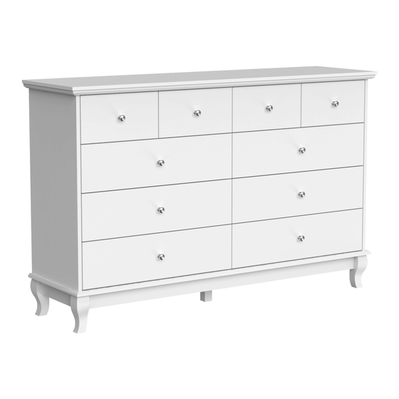
- Page 1 Dresser 1/40 Version:10/18/2022...
- Page 2 2/40...
-
Page 3: Table Of Contents
A x 20 Bx 86+1 C x 86+1 D x 2 E x 10 4 x 12 mm 6 x 35 mm 15 x 10 mm 5 x 40 mm G x 10 F x 10 J x 1 H x 80+1 K x 8 4x 35 mm 3 x 12 mm... - Page 4 4/40...
- Page 5 5/40...
- Page 6 6/40...
-
Page 7: Cl X 3
H x 12 CL x 3 CR x 3 3x12mm Fix slide rail(CR) to No.1 plate using screw(H). 3 x 12 mm 3 x 14mm Flip the plate, fix slide rail(CL) using screw(H) as shown. 7/40... - Page 8 B x 2 6x35mm Insert quickfit screw(B) into corresponding holes into No.2 and No.3 plate with a screwdriver as shown. 8/40...
- Page 9 H x 16 CL x 4 CR x 4 3x12mm Fix slide rail(CL) and (CR) to No.4 and No.5 plate respectively with screw(H) as shown. 3 x 12 mm 3 x 14mm 9/40...
- Page 10 B x 4 6x35mm Insert quickfit screw(B) into corresponding holes into No.4 and No.5 plate with a screwdriver as shown. 侧面 10/40...
- Page 11 K x 6 4x35mm Connect No.2 and No.3 plate with No.1 and fix with screw(K) as shown. 11/40...
-
Page 12: 15X10Mm
A x 2 C x 2 15x10mm Attach No.4 plate to No.2 and No.3 plate using wooden dowel(A) and turn cam lock(C) clockwise to tighten as shown. 12/40... - Page 13 A x2 C x 2 15x10mm Attach No.5 plate to No.2 and No.3 plate using wooden dowel(A) and turn cam lock(C) clockwise to tighten as shown. 13/40...
- Page 14 H x 12 CL x 3 CR x 3 3x12mm Fix slide rail(CR) to No.6 plate using screw(H). Flip the plate, fix slide rail(CL) using 3 x 12 mm 3 x 14mm screw(H) as shown. 14/40...
- Page 15 B x 8 6x35mm Insert quickfit screw(B) into corresponding holes into No.9 plate with a screwdriver as shown. 15/40...
- Page 16 C x 2 15x10mm Attach No.6 plate to No.2 and No.3 plate, and turn cam lock(C) clockwise to tighten as shown. 16/40...
- Page 17 Slide No.7 and No.8 plate into available slots as shown. 17/40...
- Page 18 E x 6 J x 1 R x 1 A x 6 5 x 40 mm Attach No.9 plate to the bottom of the unit using wooden dowel(A) and fix with screw(E) as shown. 18/40...
- Page 19 B x 16 6x35mm Insert quickfit screw(B) into corresponding holes into No.12 leg with a screwdriver as shown. fi fi 19/40...
- Page 20 C x 8 15x10mm Connect No.12 leg with No.10 plate, turn cam lock(C) clockwise to tighten as shown. 20/40...
- Page 21 C x 8 15x10mm Connect No.12 leg with No.11 plate, turn cam lock(C) clockwise to tighten as shown. 21/40...
- Page 22 C x 8 15 x 10 mm Fix the base component to No.9 plate, and turn cam lock(C) clockwise to tighten as shown. fi 22/40...
- Page 23 E x 4 5 x 40 mm fi fi 5 x 40 mm 4 x 35mm Fix No.9 plate using screw(E) as shown. 23/40...
- Page 24 Slide No.29 plate into available slots as shown. 24/40...
- Page 25 B x 10 6x35mm fi Insert quickfit screw(B) into corresponding holes into No.30 plate with a screwdriver as shown. 25/40...
- Page 26 A x10 C x10 15 x 10 mm Cover No.30 plate to the top using wooden dowel(A),and turn cam lock(C) clockwise to tighten as shown. 26/40...
- Page 27 B x 30 F x 6 G x 6 4x16mm 6x35mm Insert quickfit screw(B) into No.22 and No.23 plate with a screwdriver as shown. Fix knob(G) with screw(F) as shown. 27/40...
- Page 28 B x 16 F x4 G x 4 4x16mm 6x35mm Insert quickfit screw(B) into No.14, No.15, No.16 and No.17 plate with a screwdriver as shown. Fix knob(G) with screw(F) as shown. 28/40...
- Page 29 N x 30 4x30mm Attach No.24, No.25 and No.27 plate to No.25 with screw(N) as shown. 5 x 40 mm 4 x 35mm 4 x 30mm Slide No.28 plate into available slots as shown. 29/40...
- Page 30 N x 16 4x30mm Attach No.18 and No.20 plate to No.19 with screw(N) as shown. Slide No.21 plate into available 5 x 40 mm 4 x 35mm 4 x 30mm slots as shown. 30/40...
- Page 31 C x 30 5x10mm Attach No.22, No.23 to No.24, No.26 and No.27 plate respectively, and turn cam lock(C) clockwise to tighten as shown. 31/40...
- Page 32 C x 8 5x10mm Attach No.14, No.15 to No.18 and No.20 plate respectively, and turn cam lock(C) clockwise to tighten as shown. 32/40...
- Page 33 C x 8 5x10mm Attach No.16, No.17 to No.18 and No.20 plate respectively, and turn cam lock(C) clockwise to tighten as shown. 33/40...
-
Page 34: 3 X 12Mm
Hx 24 DL x 6 DR x 6 3 x 12mm Fix runner(DL) and (DR) to No.24 and No.26 plate using screw(H) as shown. 3 x 12 mm 3 x 14mm 34/40... - Page 35 Hx 16 DL x4 DR x 4 3 x 12mm Fix runner(DL) and (DR) to No.18 and No.20 plate using screw(H) as shown. 3 x 12 mm 3 x 14mm 35/40...
- Page 36 Align rails, slide drawers to corresponding positions. 36/40...
-
Page 37: D X 2
D x 2 L x 8 M x 8 Q x 2 4 x 12 mm 3 x 14 mm Re inforce back plate using part(L) with screw(M) as shown. Fix part(Q) to No.30 plate using screw(D) as shown. 37/40... -
Page 38: P X 2
P x 2 K x 2 4 x 35 mm Install anti-tipping device as shown. 38/40... - Page 39 WARRANTY WARRANTY CLAIMS •There is a 30-day warranty for broken furniture or any other problems that do not work properly. The warranty will start from the date of purchase which must be verified by proof of purchase. •Before making a claim, we may be able to answer your query, simply call us. Please leave your purchase order number, along with some details of the problem, if you want a replacement part.
- Page 40 RETURNS CHANGED YOUR MIND AND NEED TO RETURN YOU ITEM? PLEASE FOLLOW THE BELOW INSTRUCTIONS: •If you have purchased and have simply changed your mind, follow the retailer’s instructions for returns. DEFECTIVE ITEMS •If your item is defective in any way, i.e. it doesn’t work but you can’t identify why, in the first instance, please call us.
Need help?
Do you have a question about the KF330034 and is the answer not in the manual?
Questions and answers